Blackstar Fly 3 guitar practice amp teardown (Part 1)
The Fly 3 from Blackstar is a great little 3W guitar practice amp. It easily beats similar sized amps by competitors for volume and clarity.
Here is the description from the makers www.blackstaramps.com/uk/products/fly-3
Although it looks a bit like a toy it is actually a very well made amp which is ideal for bedroom guitarist use, silent practice with
headphones, or even busking.
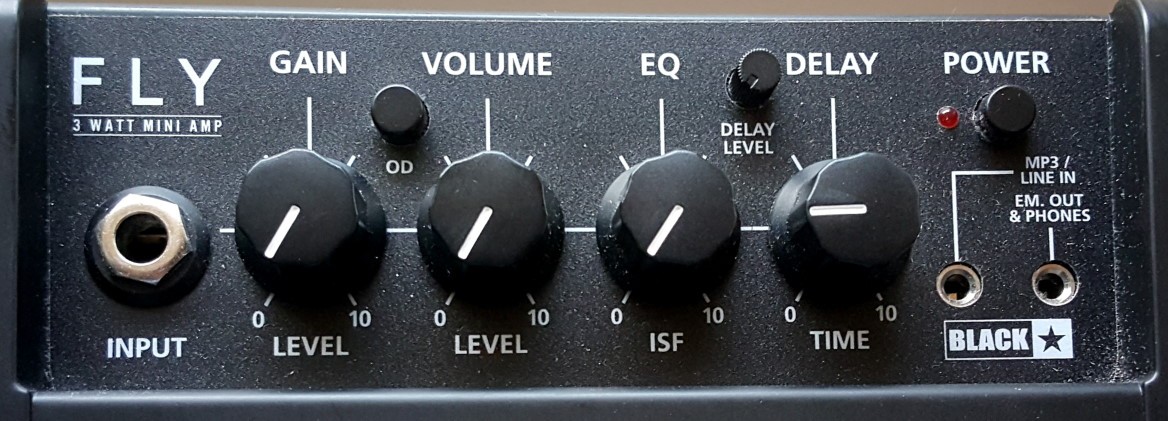
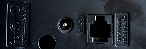
So what are its secrets? Why is it so loud and so clear for a small battery powered amp? How does it do the "Tape Delay"? What does the (optional) extension cabinet actually do?
There's very little explanation of how this amp works on the web, and I couldn't find any schematics (circuit diagrams).
So I decided to take one apart to see what's inside. As I progress I'll record what I find here. If you're easily bored by technical stuff don't read this!!
Opening the amp up
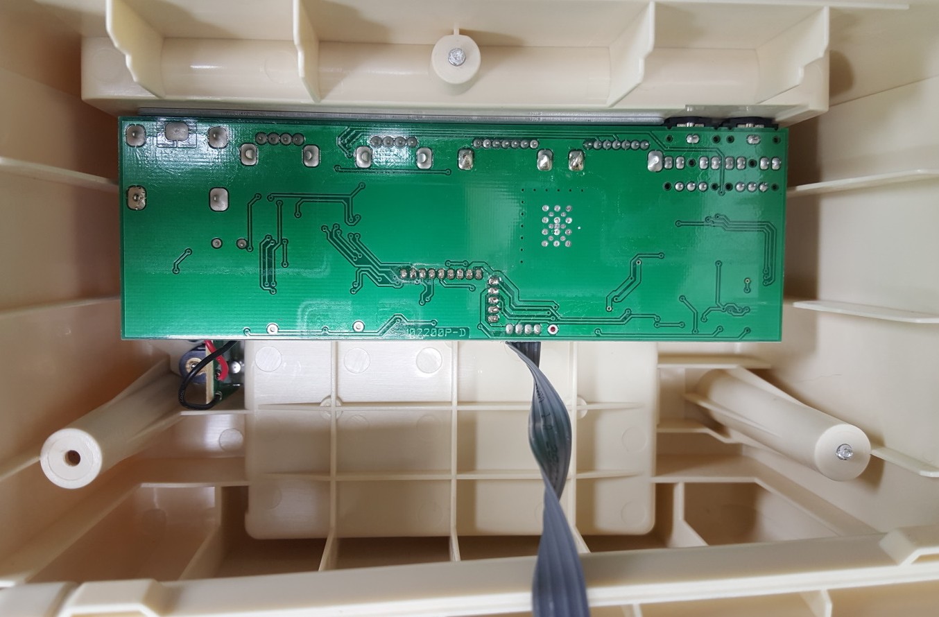
I start by removing the 3 screws from the back. These hold the front (which carries the speaker grill) to the amp body. This reveals that the speaker is screwed to the front grill and connected via a ribbon cable to a main board (PCB) which is supported at the back of the amp by the nuts on the pots and the input jack.
All the components on the main board are mounted on the reverse of the PCB so cannot be seen until the PCB is removed.
Once I unscrew the pots and input jack the main board slides out of the front panel. It has an upper daughter board, mounted via an aluminium L-bracket, which carries the Overdrive switch, the Power switch, the Delay Level pot, and the Power LED (see photo)
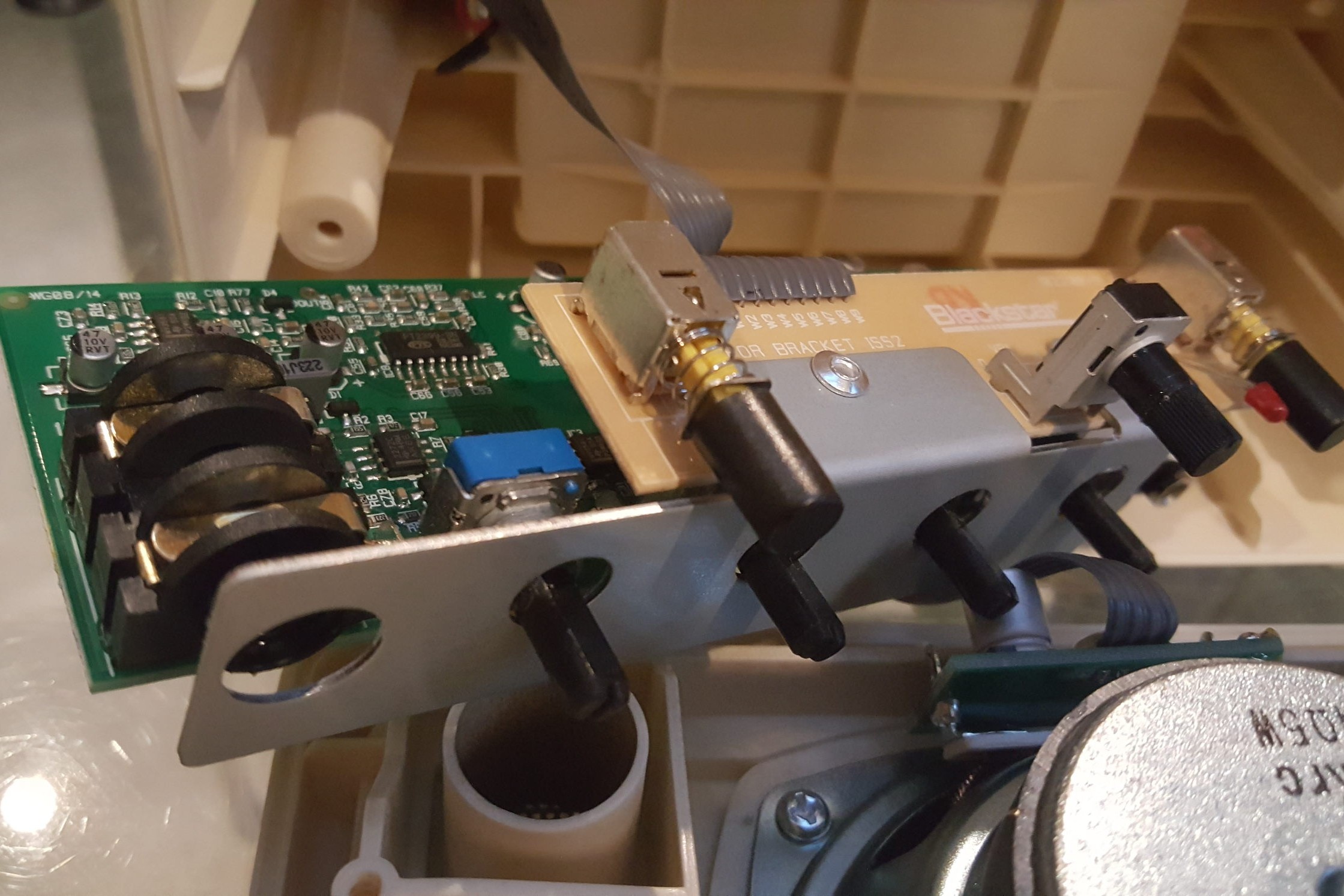
As you can see from this pic, the input jack, along with the pots for Gain, Volume, ISF (Blackstar's patented tone control), and Delay Time are mounted on the main (lower) board.
The aluminium bracket which holds the upper board in place can freely be lifted over these pots to allow access to the main board.
The ribbons are quite short making it tricky to move the boards around.
These are not the only boards inside the Fly.
One more board is screwed to the back of the amp and carries the external power jack (which takes over from the 6 x 1.5V AA size batteries in the battery compartment), and the RJ45-style connector (4 ways so I think it is RJ22) for the Fly extension speaker cabinet.
This board is connected to the main board via another flat ribbon cable. Blackstar obviously like their flat ribbons as there's aplenty of 'em.
The fourth board is mounted directly on the 3W speaker terminals and at first looks like its just some passive components between the main board and the speaker.
However on closer inspection this carries an 8-ppin IC and what looks like transistors, so it plays more of a role in the amp.
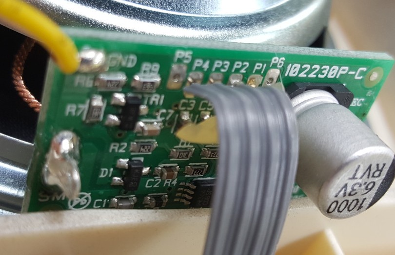
Here is a close up of the "speaker" board showing there is actually quite a bit going on including a diode, tranny, IC, and 2 inductors (which, as we shall see, give a fair clue as to what's going on here.
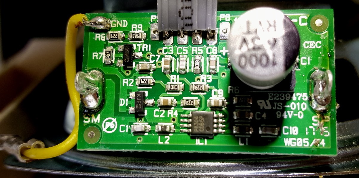
Here's some better views of the main board too.
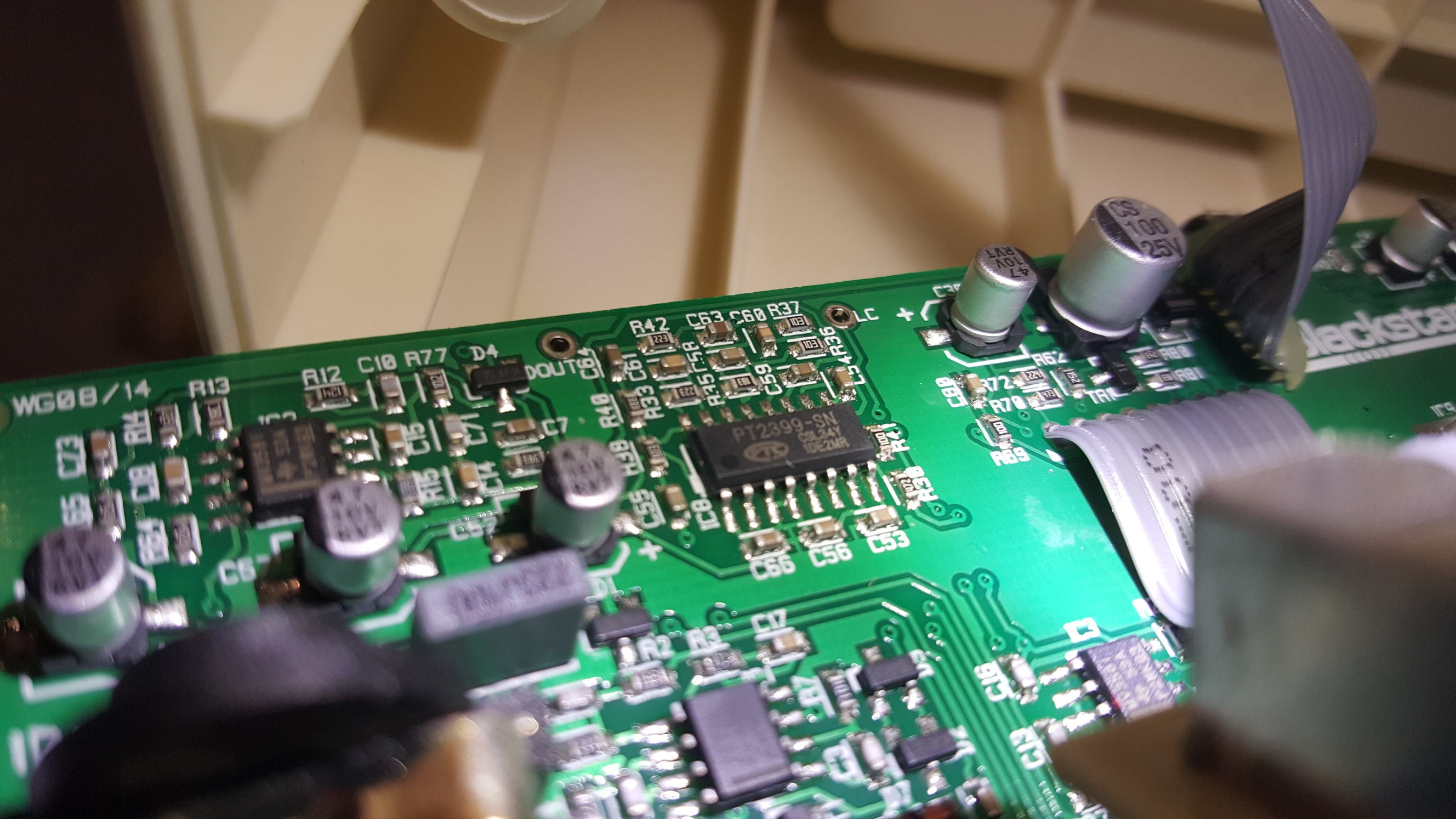
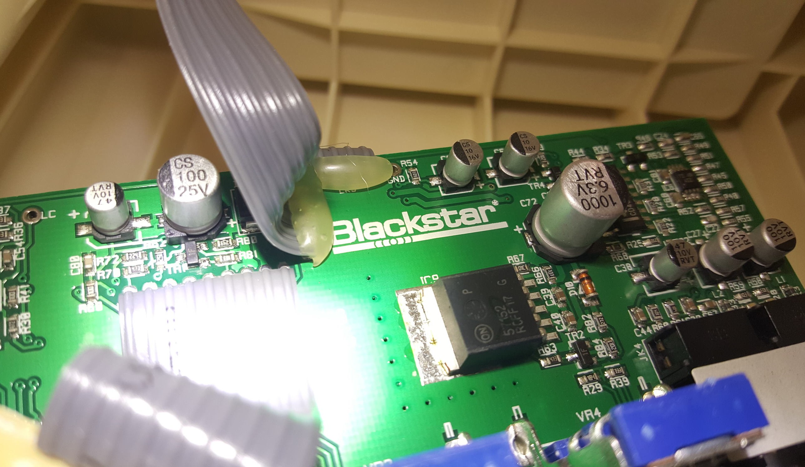
So what do the components tell us?
Initally my attention is drawn to the large IC laying flat like a box on a heatsink on the main board. It has part number "57152" and I'm expecting it to be some kind of power amplifier driving the 5W speaker (something like the Texas Intsruments LM3886 used by Peavey in their smaller solid state guitar amps) NO!! This chip turns out to be this, a 1.5A voltage regulator - in other words just a power suply IC. It gives steady power to the rest of the amp from the batteries or the external PSU. That's disappointing.
So I go hunting on the main board for another IC or MOSFETs or something that can provide the 3W to the speaker. There has to be a power amplifier somewhere in the Fly, something that can deliver high current into a speaker - the way the EL34 valves (tubes) do in a Marshall output stage.
I notice some interesting ICs on the main board though, particularly the PT2399 (we'll come back to that later). But that's all small signal stuff in the preamp stages, I'm looking for the tough guys.
Now I look back at that "speaker" board again. The 8-pin IC on it has part number "P8304". Digging around a bit on the web brings up this which is an integrated Class-D amplifier. Data sheet says "The PAM8304 is a mono filter-less Class-D amplifier with high SNR and differential input that helps eliminate noise. The PAM8304 supports 2.8V to 6V operation make it idea for up to 4 cells alkaline battery applications. The PAM8304 is capable of driving speaker loads as low as 3Ω speaker with a 5V supply maximizing the output power."
Then there are Inductors on that board L1 and L2 connected to caps C1 and C10, and terminals going straight to the speaker SM and SP. This all fits with the circuit in the datasheet.
I had a hunch this is what's called a Class-D amplifier (sorry we just got even more technical). This is a completely different kind of amplifier to your 'normal' guitar amp type thing. Its the type of tiny but loud amplifier which is used in products like your mobile phone and your Flatscreen TV. It works in a completely different way to a 'linear' amplifier which we musicians are all more used to.
Before explaining what a Class-D amplifier is there's one thing to check. If it's really a Class-D then there will be a high frequency (way, way above hearing) somewhere in the amp - that's how Class-D works. Any 'normal' (I mean linear) guitar amp with a high frequency like that has a very serious problem (oscillation). I'm assuming this amp is not very broken (it sounds fine). So an easy way to tell if its Class-D or not is break out the 'scope and look for an ultrasonic frequency in the circuit close to the speaker.
I stick my (nice new) Owon digital scope on the speaker terminal labelled "SP" and clip the probe's ground to that pin labelled "GND". Viola!!! (excuse the French)
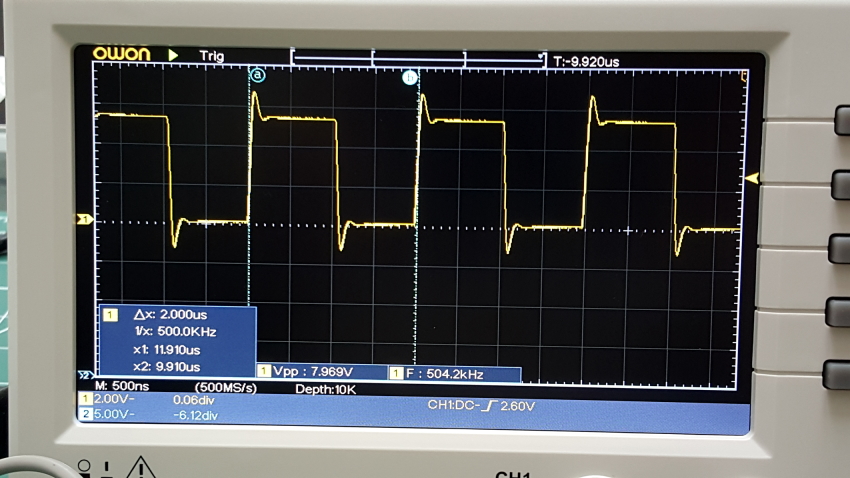
As you can see from the screen on the scope, the "SP" terminal (one end of the speaker) is happily changing from 0 volts to around 8 volts every 2 microseconds (that's 2 milliionths of a second if your timing it) which means its switching at 500kHz. That's way above even bats hearing (actually there will be no sound waves at that frequuency because there's no way the speaker cone can move in and out that fast).
You will also notice it spends the same amount of time at 0 volts as it does at 8 volts, 1 microsecond at each voltage. This is with the master volume knob at 0 so there is no signal coming through. Ignore the little spikes on the start of each edge - its nothing (much) to worry about.
This is exactly what you'd expect in a Class-D amplifier.
Now a lot of stuff is starting to make sense about the Blackstar Fly. Class-D amplifiers are very efficient. That doesn't mean they can make coffee while hoovering, it means they convert a lot of what they take out of the power supply (or batteries in this case) into sound energy in the speaker, instead of into heat. Try touching the big transistors in a conventional power amplifier when its running a speaker at high volume (IN FACT DONT DO THIS KIDS - YOU'LL BURN YOUR FINGERS AND MIGHT GET AN ELECTRIC SHOCK TOO). Conventional amplifiers are quite good at cooking bacon when they are driving hard. It makes sense that Blackstar chose this kind of cicuit for a portable amplifier where they wanted it to be as loud as possible while not draining the batteries too much. In fact very good Class-D amps are used in Hi-Fis systems now.
Interlude #1: What is so different about a Class-D amplifier?
Glad you asked!
There are things called Class-A, B, and AB, amplifiers (Ignore Class-C as it's irrelavant for audio) I won't go into what all these are (plenty on the internet) but the main thing is they kinda all work the same way.
Time for a very poor but simple analogy :)
Imagine the sound waves coming out of your speaker are temperature - I mean the hotter it gets, the more the speaker cone moves outwards.
Ok you probably think I'm nuts now but wait for this - imagine there's a man living inside your amp and his job is to control the temperature
(So I am nuts or I've been smoking something funny).
Most guitar amps work like this (gross over-simplification now follows):
The "man" inside the amp looks at how big the guitar (or other instrument) signal voltage is at the input and turns up or down a gas burner to make the temperature (the speaker cone, remember) go higher or lower to match the input. That's a linear Class-A/B/AB amp. The man constantly adjusts the temperature to follow the signal as it goes up and down, and in our analogy the temperature makes the speaker cone move more.
And the more the speaker cone moves the louder the output - so we have amplifed the pickup / mic / whatever.
Now the "man" in a Class-D amplifier has the same job as 'linear man', but he does it in a completely different way.
He watches the input signal voltage from the pickup going up and down, and according to how high the voltage is at any point in time he turns on a big beefy gas burner for a length of time and then shuts it off again. The higher the voltage he sees at the input, the longer he turns the burner on for. If its a low voltage in the waveform from your guitar pickups, then he just flicks on the burner and turns it straight off again. If its a high voltage in the waveform he leaves the gas burner on for longer.
Now what happens when the gas burner is on repeatedly for longer?
The temperature gows up gradually. And when the burner is on repeatedly for very short bursts the temperature cools down again.
So just like 'linear man' the temperature still goes up and down in response to the signal, but its a completely different way of doing it.
These gas burner bursts have to be much, much faster than the ups and downs in the audio signal voltage - in the case of our Blackstar Fly they'e at 500kHz or 500,000 times a second. The audio at most is around 10kHz or 10,000 times a second. The length of the bursts (the pulses in the speaker waveform we saw earlier) determine how much the speaker cone actually moves in or out.
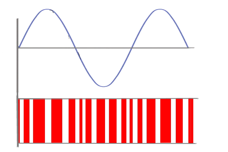
It runs out that Class-D amplification is much more efficient than the A and B classes - which as I said earlier means a cooler amp, longer battery life, and a lot louder for a given battery voltage.
In the Blackstar Fly the type of Class-D amp (yes there are different types) is of the type where both terminals of the speaker go up and down (in voltage - yes we're back to voltage now - forget the "man-in-the-amp", he's not really there you know) together. The terminals are "SM" (speaker minus) and "SP" (speaker plus), just the 2 ends of the speaker coil. When one terminal is at high voltage longer than the other the speaker coil gets more current and the cone moves more. Its a very efficient system. I could thown another analogy about 2 men, a length of wood, and a ball, but I won't.
Something to know about Class-D is that it doesn't have any of the "character" (aka musical imperfections) of something like a valve (tube) amp. It is a robotic amplifier which puts out exactly (almost) what comes in, and if well designed it does it very well. Think of it much more like a Hi-Fi amp than a guitar amp. So all the tone in Blackstar Fly 3 has to come from EQ in the preamp + maybe a bit of character in the speaker / speaker enclosure.
Here's the circuit schematic for the BlackStar Fly 3 Power Amplifier (aka Speaker Board)
I took some time to trace out the circuit diagram for the speaker board, using the photos I took above and some prodding with my multimeter, and I've hand-created the scheamtic shown on the left.
The resistor values come from what is printed on them, the cap values are not printed on surface mount components so I have not bothered measuring them.
If you look at the circuit in the PAM8304 IC datahseet you'll see it is very similar to what Blackstar created here.
A lot of the caps (C1, C6, C4, C9) are what are called 'decoupling' and are there to stop all that fast switching getting back into the power supply, and help the IC to work correctly.
Blackstar added TR1, R7, R8, and R9, I presume, to ensure the SD (shutdown) pin in the IC (pin 6) stays off when the power supply is not yet at full voltage. If there is not enough voltage across the B and E pins on TR1 then the C pin will be pulled down by R9 and the SD pin 6 on the IC will be near 0 volts - meaning the audio output of the IC is muted.
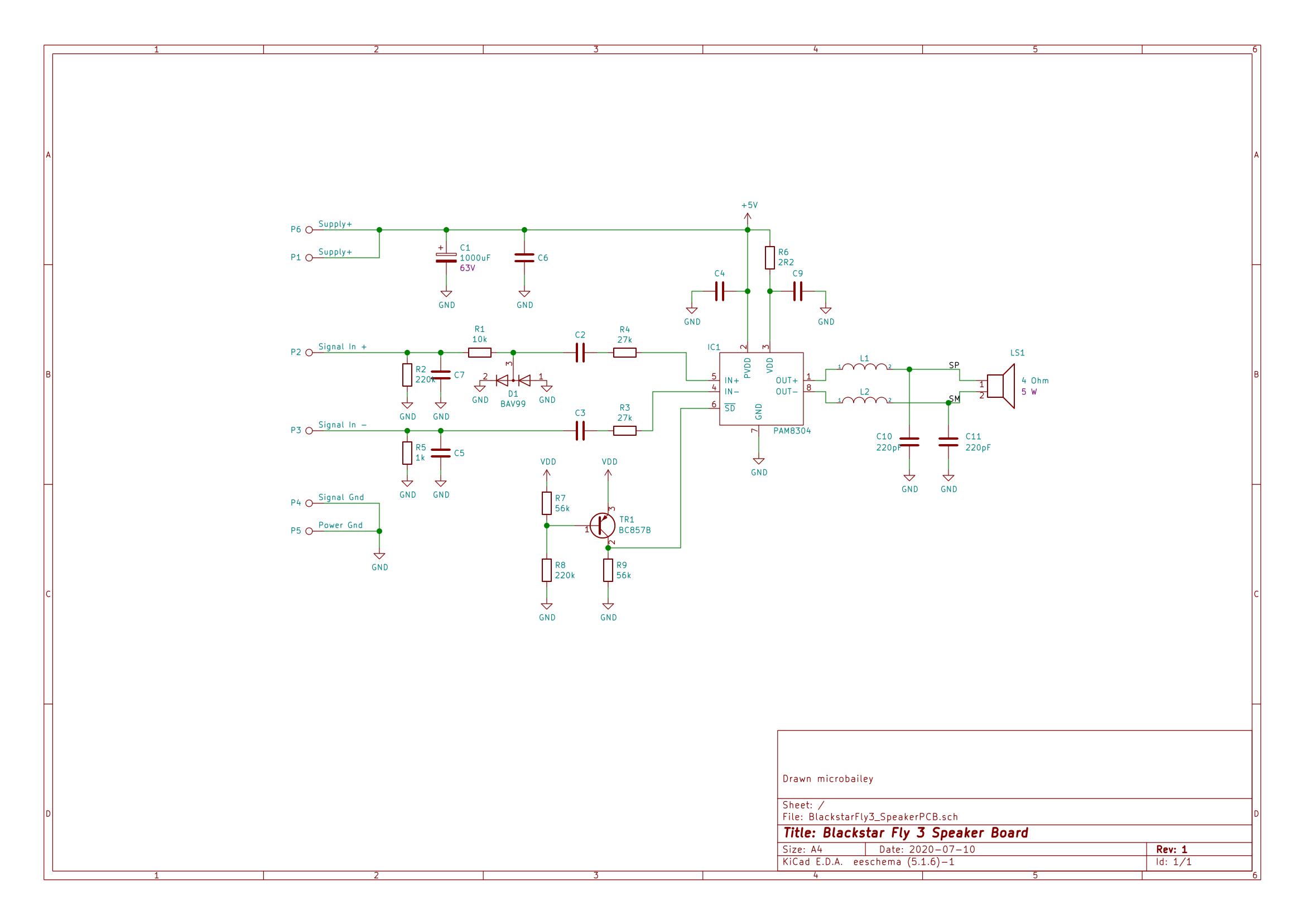
Schematic for Blackstar Fly 3 Guitar Amplifier Power Amp PCB
All the business with the + and - audio signal inputs probably deserves some mention. This IC takes what is called a 'differential' signal meaning the signal has two wires, a + (plus) and a - (minus). When the + is positive voltage compared to the - that means an overall positive voltage, and when the + is negative voltage compared to the - that means an overall negative voltage. This type of circuit is more immune to noise pickup (I mean electrical noise or what you might call interference, for example from a nearby mains PSU) - it works a bit like a humbucker pickup where the same magentic noise (for example from a nearby mains lead) gets cancelled out just leaving the real signal.
Now we have the schematic for the power amplifier there's something interesting here ...
What is interesting is that we have a completely self contained power amplfiier on a little board (if you don't know what a power amplifier is - it means the part of your amp which has enough oooomph to drive the speaker directly). You will notice that there is a 6 pin input connector on this speaker board with power supplies V+ (2 pins doubled up), Ground (2 pins doubled up), Signal In+, and Signal In-. Now the Blackstar Fly 3 can have an extension speaker attached to it - and I had assumed this was just a speaker in a box, but what if the extension speaker cab (Blackstar call it the Fly103 - Here's the link) also has this same board to drive its speaker? Well the jack on the back of this amp has 6 pins so that would match the 6 pins on this board. Hmmmm.
Time to get hold of a Blackstar Fly 103 Extension Speaker and open it up to see what's inside.
Inside a Blackstar Fly 103 Extension Speaker
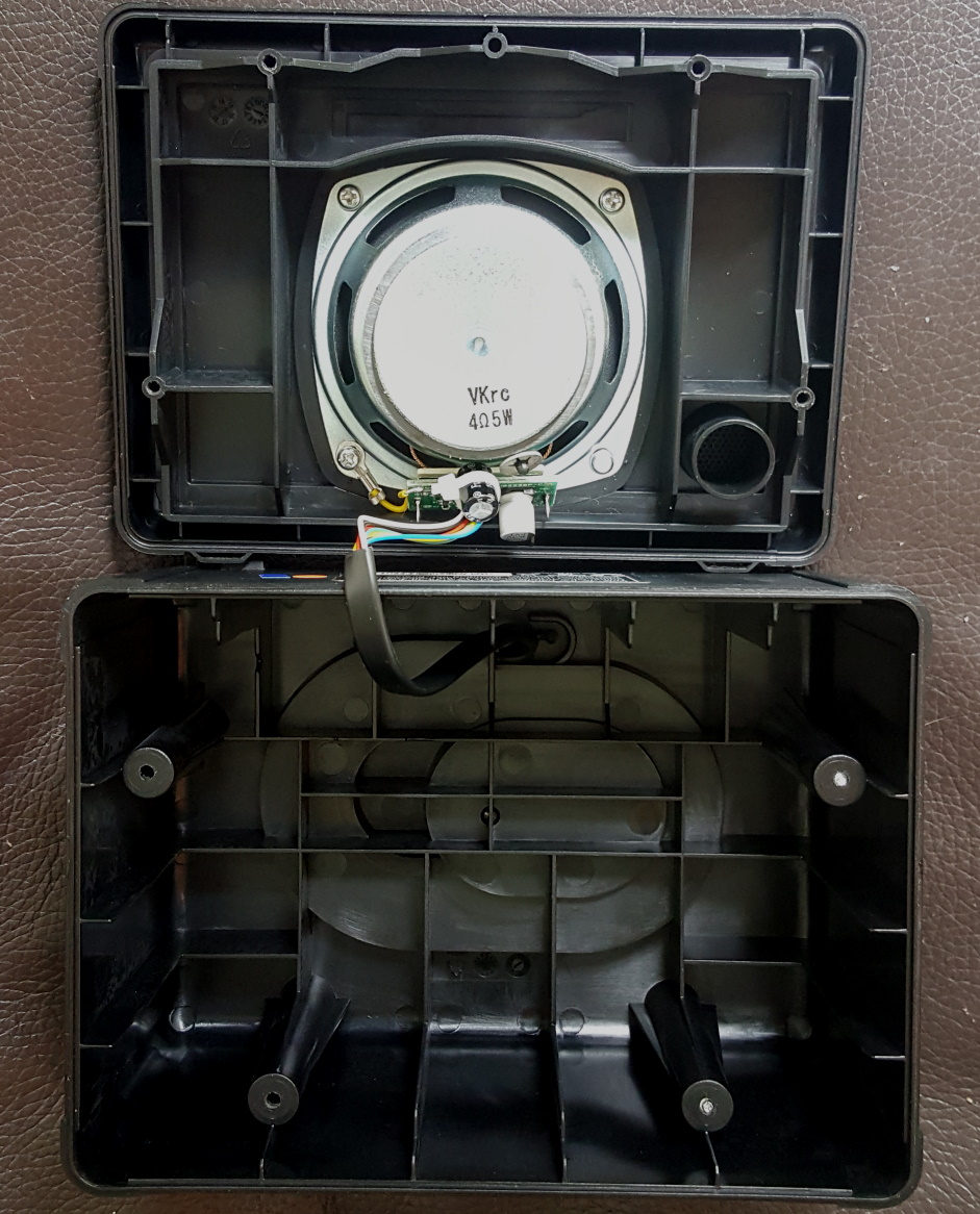
Here's an opened up Fly 103 Extension Speaker. Not much to see?
Yes there's a speaker but - look - there's also a little PCB mounted on the speaker just like the one we have in the main amp.
And - look - the ribbon cable from the speaker board runs straight out of the back of the cabinet and it has a plug on it which plugs into the rear board in the main amp.
Here's a close-up of the speaker board in the Fly103 cab.
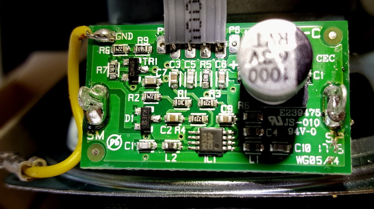
Why this is interesting (I find lots of crazy stuff interesting) is that if I buy a Fly 103 Extension Cab (costs around £24 new in the UK) I have a nice little Class-D amp board, with a good sounding little speaker, and a proper solid cabinet (I might say more on the design of the box from an acoustic point of view later - you may have noticed that 'sound hole' in the front next to the speaker ...). And the whole thing runs off 5V DC (on the outer cores of the cable in the cab).
In other words - if you wanted a good basis for creating your own DIY amp for Guitar, Keyboards, anything really, this is a nice way to do it. And there is loads of space in the cabinet for your own PCB / Stripboard / tagboard / whatever.
Having a Power Amp in each cabinet makes sense, since Blackstar advertise this as a way to have stereo speakers for your PC, and we have seen the main amp only appears to have a 1-channel power amp.
Back to the main amp now.
The Rear Board
I'm calling this the 'Rear Board', the PCB that is mounted right at the back of the Blackstar Fly 3 main amp enclosure. It has a jack for power and a jack (that looks like an Ethernet connector) and I see wires going to the batteries too. Here's a picture of it, and another of the underside where the PCB tracks are routed. It's a cheap single sided PCB.
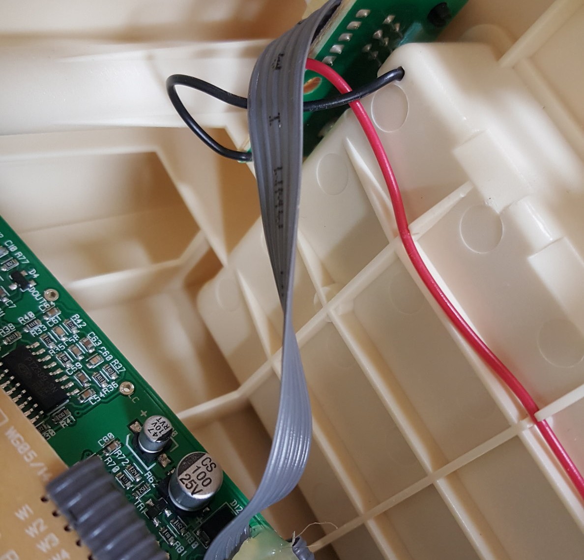
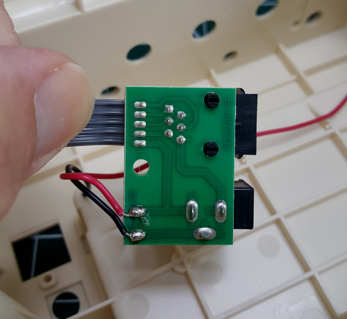
I'm going to trace this board and draw aschematic for it, just to make understanding the amp easier.
You'll see quite clearly from the tracks on the left that the Black from the battery (-ve wire) goes through the Power jack on its way to the "Ethernet" style conn (for the Extension Cab) and the ribbon (which goes to the Main Board).
That means the -ve rail from teh battery gets switched out for the external PSU when its plugged in. The Red, you can see, goes straight to the ribbon - so it's not switched.
'That "Ethernet" style conn is actually a 6P6C RJ25 connector (Ethernet, RJ45, has 8 pins, this only has 6 pins).
I traced the schematic for this tiny board and I got this:
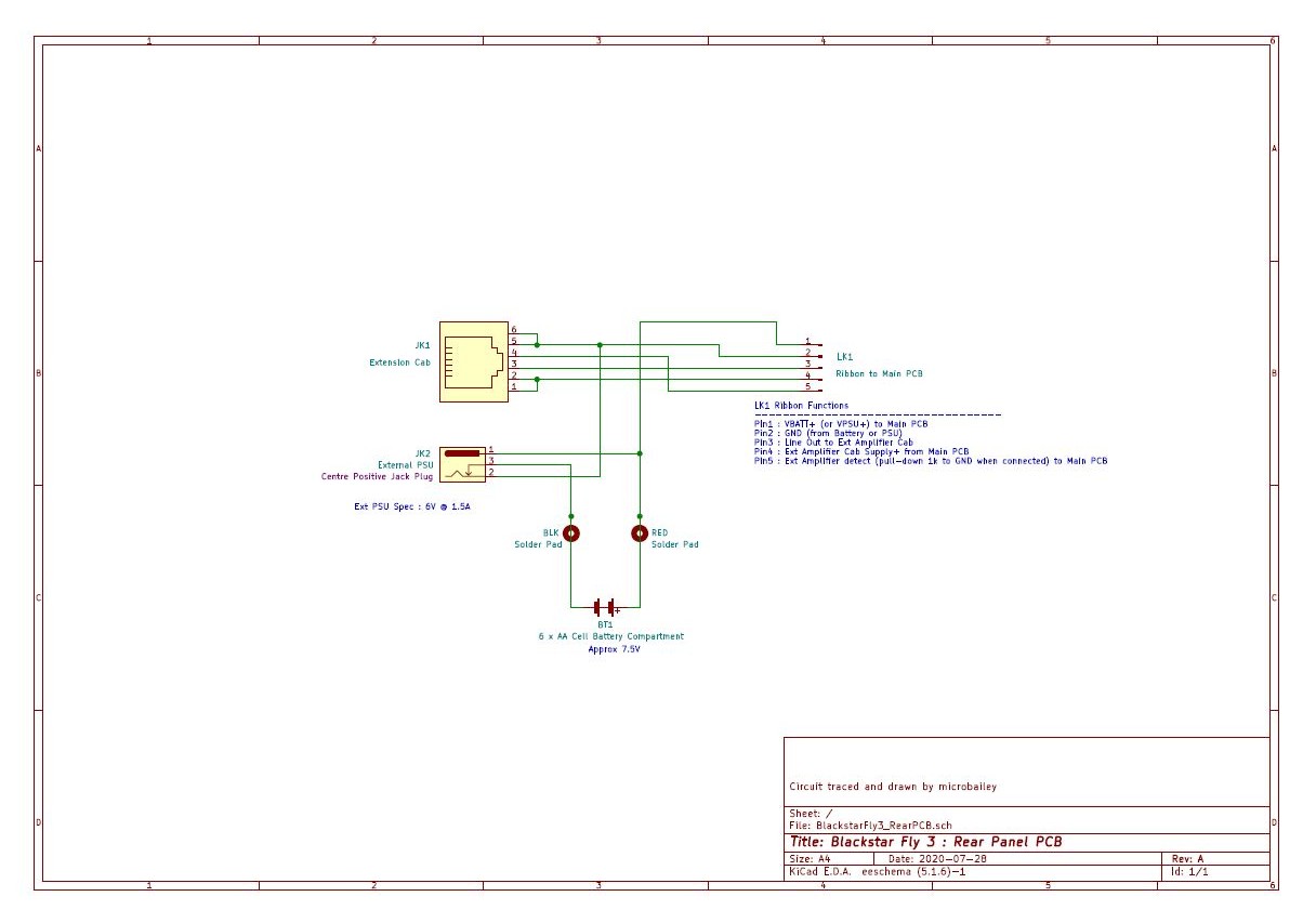
Schematic for Blackstar Fly 3 Battery, External Power, and External Speaker PCB
I've listed out what the pins on the 5-way ribbon which goes to the Main Board do. I've deduced their function by tracing some of the Main Board (results coming up next) as well as looking at where they connect to in the Fly103.
All the pin functions are probably self-explanatory except PIn 5 Ext Amplifier Detect. If you compare it to the Speaker Board schematic you'll see that goes to the Signal-. So why did I call it Ext Amplifier Detect?
By tracing the Main Board I figured out that, although this pin is used as the Ground for the signal going to the Extension Amp (on PIn 3) it also does another job. The Speaker Board has a resistor between Ground and Signal In-. I found out that the Main Board uses this to detect when the Extension Amplifier is plugged in. Why does it need to do that?
Wait for me to start explaining what the Main Board does!!!
Finally - because the Ext Power jack outer disconnects the -ve from the battery, you see why it is wired as inner-positive. This is the opposite to most stompbox power jacks so watch out using the Fly with another PSU!
Blackstar Fly 3 interal layout
I'm talking about Rear Board, Main Board, Speaker Board, Surf Board, ... It's probably time to draw you a sketch (based on my notebook sribblings) of what is where and how it all connects together. Looking at the sketch I've made below, LK1, LK2, LK3 are flat ribbons which interconnect the various PCBs. Hopefully this makes things a bit clearer?!?
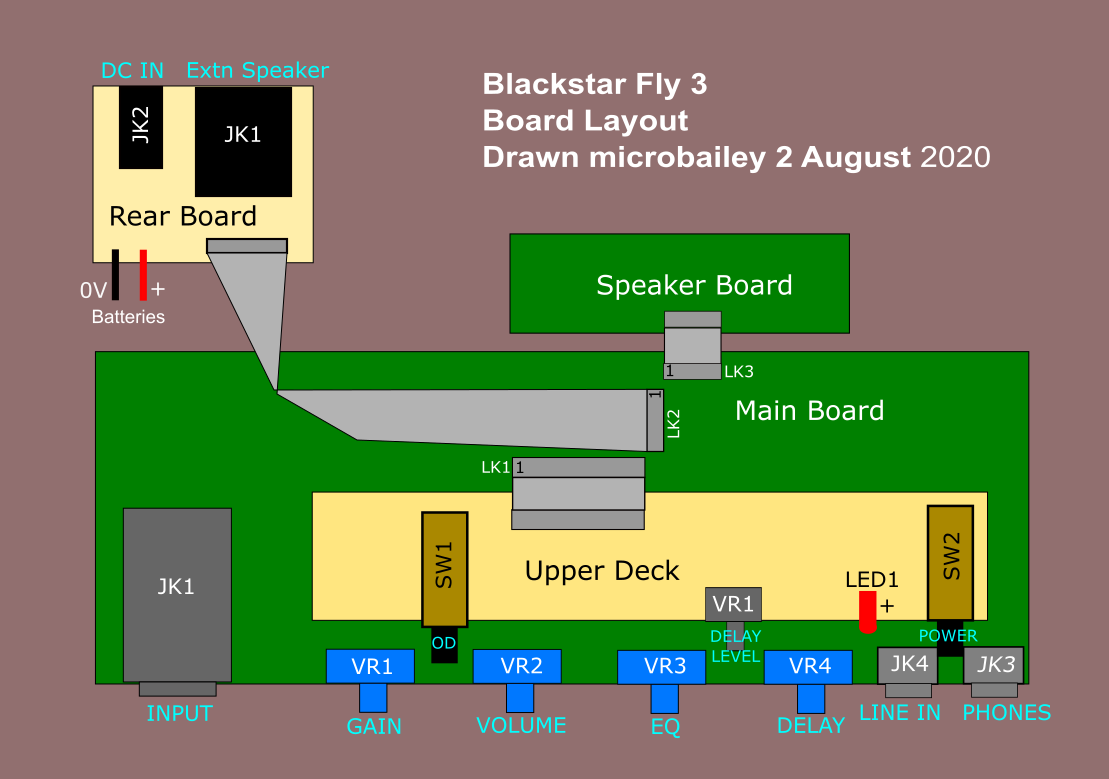
Blackstar Fly 3 Internal PCB Layout
And so to the main board itself!
Well this is where most of the magic happens so let's get on with it.
I've been struggling to get time in the last couple of weeks to do tracing of the main board, but as you can see from my scribbles in the notebook here, I have been doing something. Its very time consuming to trace a surface-mount PCB like this, partly because PCB tracks disappear under things like vertical capacitors and connectors, meaning 90% of the connections are quickly traced and the other 10% take 4 hours!
I've not been able to accurately measure all capacitors (SMD capacitors don't usually have any markings - so the only way to determine the value is a meter). Where I'm not sure I'm just going (for now anyway) to say there is a cap and whether it is polarised. In many cases the cap (capacitor) value doesn't really matter all that much and it might surprise you that most 'everyday' caps have values all over the place anyway.
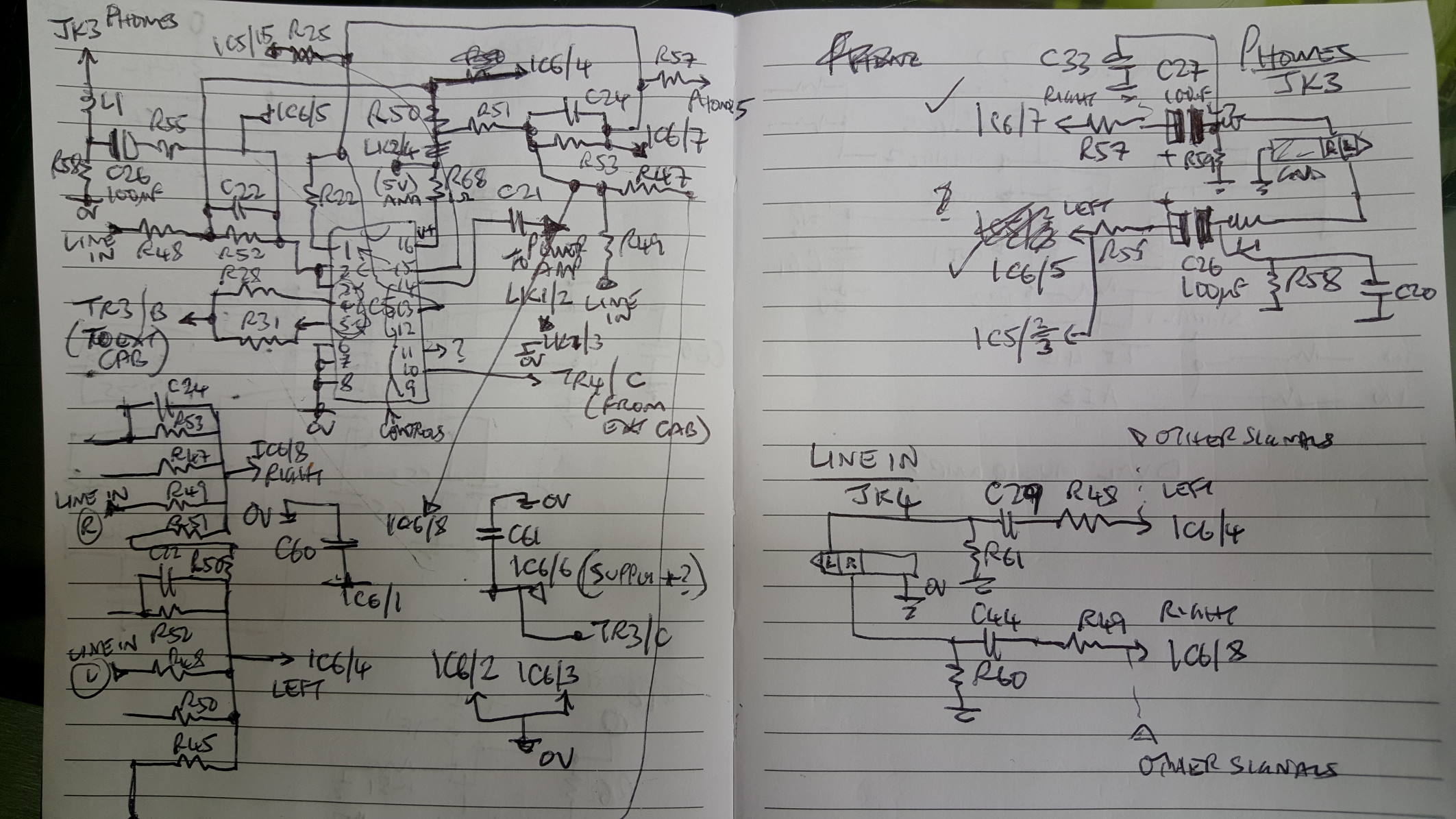
The headphone amp and the signal routing section
For some bizarre reason I decide to start at the end of the signal chain and trace back. I'm not sure why I did this, but I think it was partly because I wanted to know what drives the extension speaker connector on the rear (see above)., and that led me into this part of the circuit.
It makes sense to divide up this board as there's quite a lot going on.
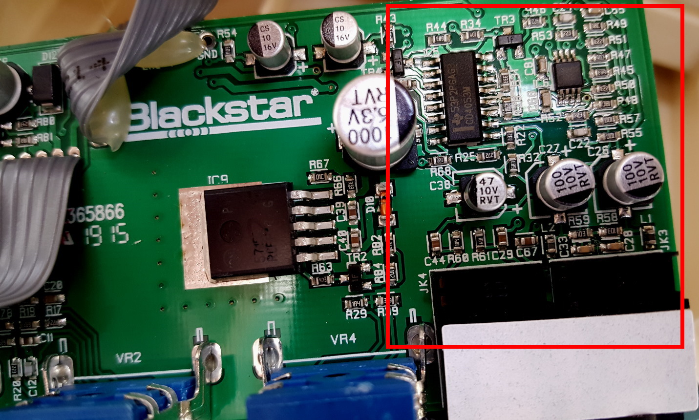
So what I found was that there is a "mystery" 8-pin IC (Integrated Circuit = the things that look like leggy bugs on the board) in this section, and another easily identifiable 16-pin IC.
- The mystery IC has the marking "TI AB AIZ" which instantly meant nothing to me.
- The easy IC had the marking "CD4053M" and a little symbol the shape of Texas. Now that instantly meant analog switch to me (the symbol like Texas tells us that Texas Instruments made this IC)
The 4053 is one of a family of analog (analogue in the UK but I'm trying to be more international here) switching ICs which are great for audio design since they act just like - well - switches. Except instead of having a push botton or a footswitch, they have a digital voltage input which is either '1' (near the V+) or "0" (near GND) and this switches between 2 inputs. In the case of the 4053 there are actually 3 of these changeover switches - they change over between 2 analog inputs or in this case 2 audio signals form somewhere. Now just like real swicthes they can work in reverse and take one signal and send it to one of 2 different places (think an A/B footswitch pedal).
So the presence of the 4053 told me there is some signal routing going on - perhaps under the control of the front panel switches?
Also this IC is very close to both the Phones and External Line In jacks, suggesting that the switching might be to do with those.
As for the mystery IC I searched on the web, searched again, searched another 6 times, and then gave up. I couldn't find anything under TI AB AIZ.
I had already assumed that the TI was - again - Texas Instruments (they make a LOT of different ICs, and I mean a LOT), but the Ab AIZ turned up nothing. Then a few days later I thought - maybe the AIZ is a code for the actual part number?
So to understand this you need to know that because surface mount components are very small, often the full part code can't be printed on them. That's the case with resistors where sometimes a code is used to represent the full value (see this website for more info http://www.resistorguide.com/resistor-smd-code). This can apply to ICs too, so I searched the web for a TI code lookup - to see if the code AB AIZ was short for a longer part number.
That's when I found this on the Texas Instruments website: https://www.ti.com/packaging/docs/partlookup.tsp
It is a search box for TI surface mount part codes. I entered AIZ and BAAAAAAA-A-A-A-MMM!!!!!!!! it came up with
| TPA6110A2DGN | AIZ | DGN | 8 | ACTIVE | 150-mW Stereo Headphone Audio Amplifier, Pin Compatible with LM4881 |
which sounds exactly like the sort of thing you'd expect in an amp with Headphones.
I had already, from tracing the board, started to suspect it was some kind of op-amp (a type of signal amplifier) because of what was connected to it, but it had a really wierd pin-out (most op-amps have the same pin-out, whcih means which pin does what).
So now I could get a datasheet for the TPA6110A2DGN. Here is is here
The datahseet was a huge help in confirming that I had the right connections on my traced schematic.
Armed with this, some Googling of the JK3 and JK4 jack socket pinouts, a lot of metering and prodding, and a magnifying lens, I came up with this - the first part of the Blackstar Fly 3 main board, covering the Phones Amplifier and Signal Swicthing. Schematic was drawn by me using KiCad.
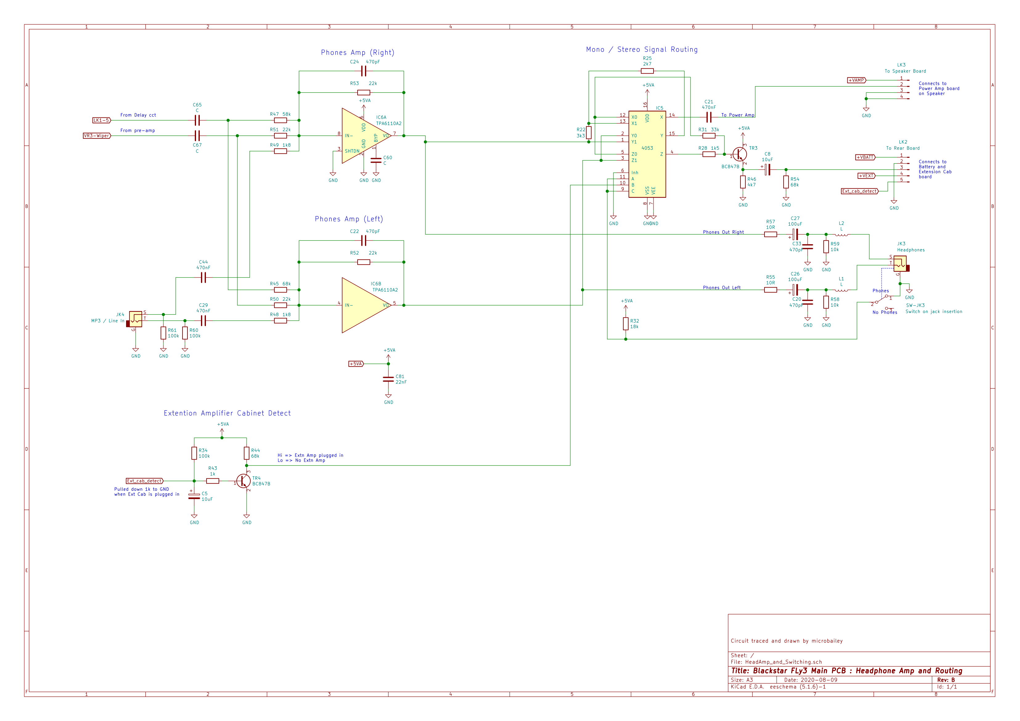
Blackstar Fly 3 schematic for Mixer, Headphone Amplifier, and Audio Switching section
So how does this work and what does all that switching in the 4053 IC do? Read on and I'll explain (or at least give my best guess).
Circuit analysis of the signal mixer, headphone amplifier, and signal switching section
So how Well now we have schematic we can quickly see that tiny 8-pin IC6 is doing the heavy lifting of driving the headphones output as well as acting as a mixer for various signal sources. And IC5 (as already said) is doing some nifty signal routing to various places.
Lets start with the input mixer into IC6.
Mixer and headphones amp
So how Well now we have schematic we can quickly see that tiny 8-pin IC6 is doing the heavy lifting of driving the headphones output as well as acting as a mixer for various signal sources. And IC5 (as already said) is doing some nifty signal routing to various places.
Lets start with the input mixer into IC6.
IC6 has 2 halves and each is a high-output drive op-amp. I won't explain how op-amps work here, but if you want to understand them much better try here For the purposes of our discussion, an op-amp is an easy to use amplifier with 2 inputs (+ and -) and an output.
In this type of circuit called summer-inverter (no there isn't a winter version) we can mix signals together easily into the "-" input just using resistors. The value of each resistor sets how loud the signal is in the mix at the output pin (lower R = louder).
So here we are mixing 3 sources:
- "Delay" output via R45 and R47
- "Pre-amp" (from the master volume - we haven't looked at that yet) via R50 and R51
- "Line-in" which is coming from stereo 3.4mm jack JK4 via R48 and R49
The two halves of IC6 (labelled "A" and "B" in my schematic) are handling Left and Right audio. We might have forgotten that Blackstar Fly 3 is also marketed as a stereo music amp (for use with phone etc) so that's why we have a stereo amp here.
If we just look at the stereo Line-In/MP3 JK4 through IC6 to the Phones out JK3 it's all very straightforward stereo amp.
What about the mono from the Delay and Pre-Amp sections? It is just fed into both L and R amps (the way you would use a splitter cable to feed a mic into a L and R phono jacks on a console).
It's interesting what happens to the L and R outputs of the IC6 though.
Signal switching and routing
As well as providing headphone L and R, IC6 is feeding a stereo signal into IC5 which is being used to switch siganls around on the Fly's outputs.
IC5 is not so easy to understand from its schematic symbol. I've tried to draw a view of what is inside here:
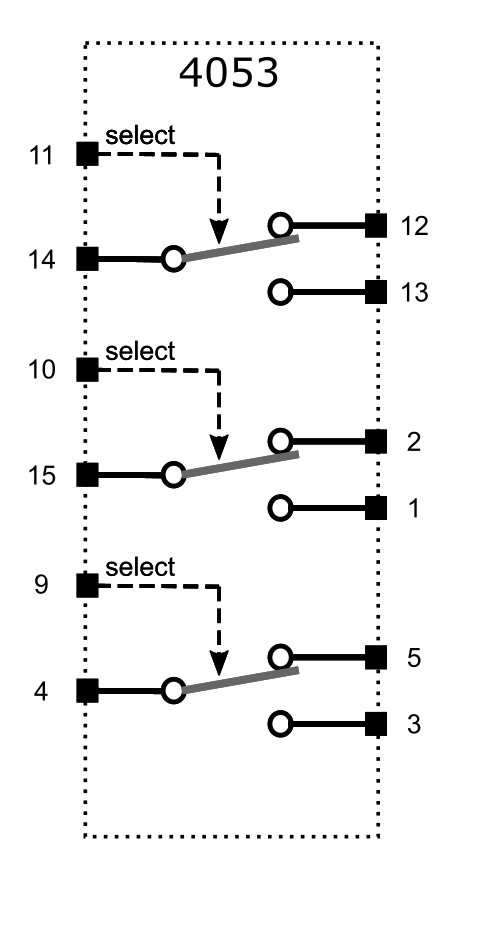
4053 analog switch IC schematic
Imagine an A/B switch which sends an input signal to one of 2 outputs (exactly what and A/B pedal swicther does, where it might go to 2 different amps). Now instead of that switch being operated by a hand or foot (or headabutt as I once saw someone do to his amp-muonted pedal), this switch is operated by a voltage. When the voltage is near the supply (+5v in our case) the switch goes one way, and when the voltage is near the ground (0v) it goes the other way. And no it does do both when the voltage is in the middle. In fact the mid-voltage is not allowed.
Well you get 3 of these voltage-operated A/B switches in a 4053 IC in a 16-pin DIL package. There is another input which can turn all the swicthes off but the Fly does not use that.
What you will see if you trace where the L and R are going in and out of IC5, is that Blackstar have created a switcher which routes signals depending on whether we are in a Mono or Stereo configuration.
Perhaps obviously, if there is only one speaker (the main amp in the Fly 3) then we can only be mono, and everything gets mixed down to mono.
If there are 2 speakers (FLY103 is plugged in) then we get R on main amp and L on the remote amp.
How does the Fly 3 (main amp) know if the FLY103 (extension) is plugged in? Remember that on the Speaker Board schematic there is a 1k resistor (R5) to ground on the "Signal In -" input. When this is plugged into the Fly main amp this wire gets connected to what I have labelled "Ext_cab_detect" in my schematic. That has the effect of pulling the voltage on TR4 base pin towards 0v, and that causes TR4 collector to move towards +5v (since TR4 is switched off). This provides the voltage to the select pin for number 2 of the 3 switches in the 4053.
I wont explain all the combinations of the 3 switches (it took me a while to get my head around it) but I've summarized it in the Table below:
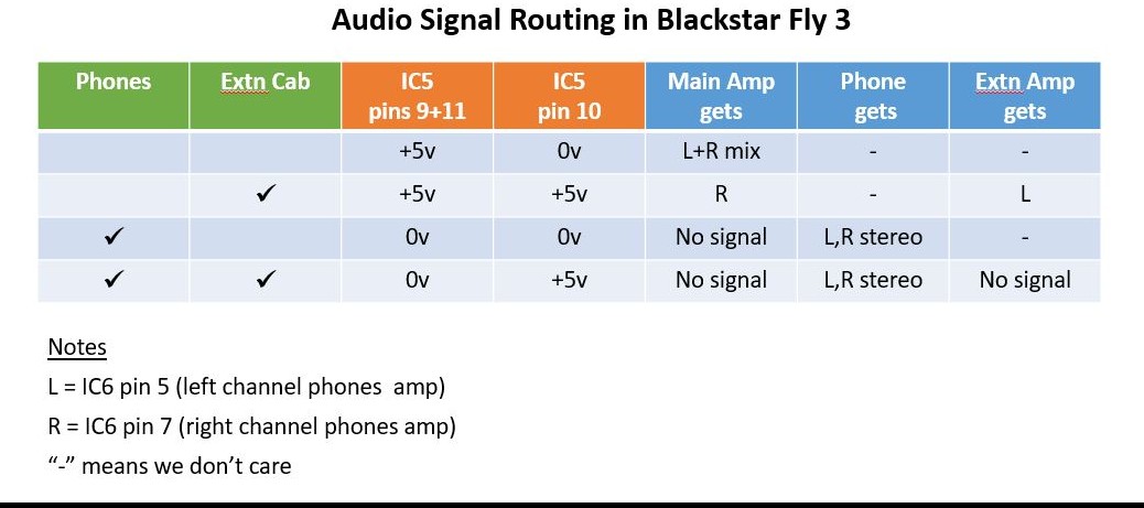
Table of signal switching and routing in Blackstar Fly 3
The reason we have some outputs marked as "-" dont care is that we dont care what is fed to the FLY103 if its not connected or to the Phones when nothing is plugged into that jack.
Its quite a neat switching circuit and was definitely a complicated piece of tracing work since I had no idea what I was going to find.
You'll notice I've called the positive supply for IC5 and IC6 +5VA. That's because is it isn't exactly the same pice of wire as the +5V on the Speaker Board. Once I've traced the power supply distribution inside the Fly 3 I guess I'll better understand how this is all connected.
For now I can say its quite common to separate supply rails in circuits to reduce electrical noise getting from one part to another.
Final word about TR3. It has the signal from IC5 for the Extension Cab on its base and then drives the lead to the cab from its emitter pin. This circuit is called an "Emitter Follower" (read more here) and it does exactly what a Buffered output from a Pedal does - it drives a long cable with less loss of the highs. The cable on the Ext Cab is not very long but we could still have trouble connecting it directly to IC5 pins.
"Tape" Delay circuit
And so I moved on (backwards in terms of signal chain) to the Tape Delay.
The Fly is supposed to emulate a Tape Delay (old skool echo where actual magnetic recording tape moved past one or more playback heads and went round in a loop to be used again - try Googling "WEM Copycat" if you're interested in the history of this type of early effects technology) . A characteristic of the original tape delay was that the echos lost high-end very quickly due to to EQ used to reduce hiss buildup on the tape - we'll come back to that when we see how the Fly has done this with solid state tech. Original Tape Echo machines had some fantastic imperfections which unfortunately the Blackstar Fly does not emulate.
To be honest though, I wouldn't have really expected an anlog delay in an amp of this size and price anyway so the delay feature is a bonus.
There are 2 controls for Delay on the Fly front panel:
- DELAY TIME which adjusts the delay time from what sounds to me like ADT (automatic double tracking) up to quite pondering echoes
- DELAY LEVEL which adjusts the amount of echo in the final mix at the speaker / phones
The part of the main PCB concerned with Delay is shown to the right.
The main IC doing the business here is the 16pin DIL IC8 which is an industry standard PT2399 made by Princeton Technology Corp. This is used in a number of current guitar pedals to do exactly the same thing as it's doing here - emulate tape delay (the IC is actually for karaoke machines but that's another story).
I spent a few happy evenings tracing the circuit out from the PCB and drew up what I found as the schematic lovely here. Many thanks to member ppluis0 on freestompboxes who helped me find the pinout for the Marshall style dual-gang pots which are used on the Fly (I think they are made by Alps).
I'll explain what is going on in the next section.
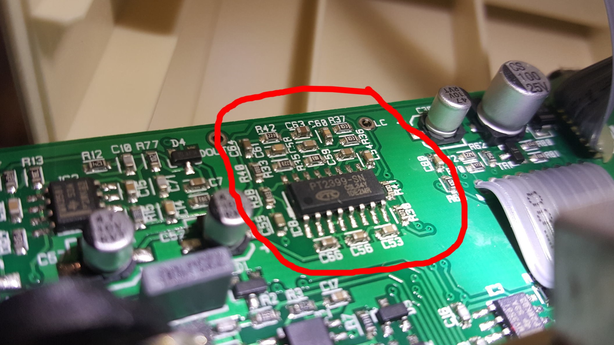
Main PCB showing Analog Tape Delay circuit

Main board : Analog Tape Delay schematic
Circuit analysis: Analog "Tape" Delay
So we have a PT2399. This IC is actually a digital delay chip, and includes ADC (Analog Digital Converter), DAC (Digital Analog Converter), and digital memory (which forms the delay part of the Delay). Basically the analog input signal gets converted to digital, written to digital memory, read back out some time later (set by the on-chip oscillator - more in a minute), and then converted back to analog. In the circuit Blackstar have used here the signal goes in on pin 16, and comes out delayed on pin 14.
The PT2399 uses a type of ADC called Sigma-Delta which is very good for audio and gives a much lower level of background noise to the delayed signal than older types of ADC would have done (say in a Digital Delay from the 1980s). This type of ADC needs a sampling frequency much, much higher than audio frequencies to work properly. Sampling frequency is a measure of how often the incoming audio analog signal gets frozen and turned into a number. CDs do this 44100 times a second (= sample rate of 44.1kHz). A studio pro recording will do this 96000 times a second (96kHz). The PT2399 appears (its not clear form the datasheet to be honest) to sample at over a million times a second, ie. the frequency, or maybe half the freequency of that oscillator inside the chip. An oscillator is just a signal (like audio) which has certain frequency or pitch, in this case way above human (or even dog) hearing.
So speaking of the oscillator, on the right here is a table, spread across 2 rows, taken from the Princeton datahseet showing the delay we get (in milliseconds) by altering the osc frequency. How do we alter the osc frequency you ask? Well the PT2399 manufacturer recommends we do it by altering a resistor between pin 6 and Ground (0V). The table shows the resistance in ohms, the frequency we get, the delay we get, and something called THD (Total Harminic Distortion). We'll come back to what the THD means in the Blackstar Fly context later.

PT2399 Delay vs Resistance table
The reason the osc freq alters the delay has nothing to do with the ADC, which will also use this frequency. Instead it is to do with how fast the counters advance which address the memory, or in other words how long between each audio sample being taken back out of memory.
For the Delay circuit in the Fly we have a 50k linear pot (VR4) in parallel with a 180k resistor (R29) , all of which in series with a 4k7 resistor (R30) going between pin 6 and GND. This gives a variable resistance from 4k7 (at the fast end of the DELAY TIME pot) up to around 44k (at the slow end of the pot) . From the table that means we get a delay from about 83msecs to (I'm extrapolating) around 600msecs. The actual freqeuncy of the osc can be measured at IC8 pin 5 so I should really find out what it is at the low end with a frequency meter.
Delay circuit filters
It is not at all clear from the badly written Princeton data sheet, but there are six op-amps (operation amplifiers) inside this chip. I could not do better than to refer you to the excellent Electrosmash discussion of what goes on inside a PT2399 here: https://www.electrosmash.com/pt2399-analysis This webpage makes the confusing PT2399 datasheet a lot easier to understand.
3 of the op-amps are used in the Fly circuit as filters (circuits which attenuate or amplify certain frequencies) directly in the audio path through the delay. These are:
- Input filter op-amp pins 15 and 16. C61 and R33 start attenuating frequencies above 2.6kHz
- Output filter op-amp pins 11 and 12. C59 in parallel with a 4k7 resistor inside the chip starts attenuating frequencies above 413Hz YES that's 413 Hz !!!
- Final output filter op-amp pins 13 and 14. This is a slighty more complex filter circuit which I've re-drawn as the schematic here on the right. Ignore the component refs - they are not from the Blackstar Fly 3 board, but the component values shown are.
Below is the result of an LTSpice simulation of this final output filter, just to establish the frequency where it starts to have a noticable effect. LTSpice is a free simulator and in this case I have simulated the filter circuit with a model of an ideal op-amp.
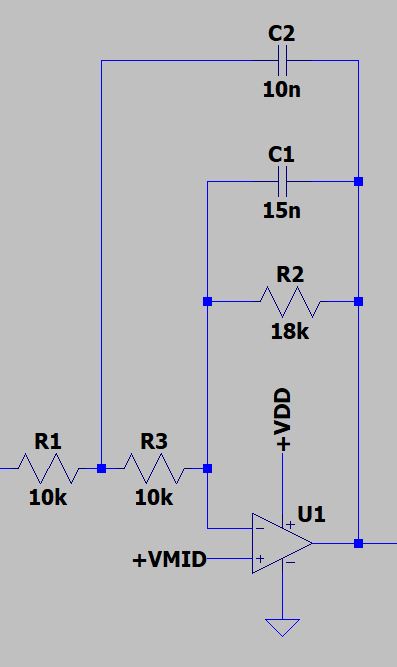
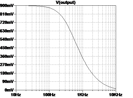
From the simluation plot you can see this filter (#3 in the list the above) starts taking effect around 200Hz and halves the signal voltage when we get to about 600Hz. (I know there is a much more formal way to describe a filter in terms of -3db cutoff etc but for the purpose of this analysis I'm just giving a feel for what the filters do).
So those 2 output filters on the delayed signal take off a lot of the top-end. Remember, saying the filter starts attenuating at 413Hz doesn't mean (for this type of filter) that all the frequencies above this disappear. It just means they are quieter. This darkens the sound of the repeats(s) very significantly.
So this nicely emulates a Tape Delay - I said earlier that a Tape Delay loses the higher frequencies very quickly because of the noise suppresion circuitry at the time. This means there is scope for DIY mods to the component values here to add a lot more high-end back in if a more natural sounding echo was wanted on the Fly.
Before leaving the subject of the Delay EQ character, let's talk about the THD figure. Remember that table earlier where THD number goes up as .delay time gets longer?
Well the THD can be thought of as a measure of how overdriven the audio sounds. Higher THD = more added harmonics = more overdriven sound. So as the delay time on the Fly goes up we can see the sound of the delay gets more overdriven sounding. This was another characteristic of Tape Delays - a slightly overdriven sound - so again this THD effect is good for a Tape Delay emulation, when set at longer delay times. At shorter delay times the THD is lower and we get a sound which is a crisper copy of the original, albeit darker.
Clever combo delay repeat feedback circuit
One of the features of the Blackstar Fly's delay circuit is that there are repeat echos, but these can't be heard when the Delay pot was near minimum delay time. I'd not thought about this much until I looked at the Tape Delay schematic when I see it now makes sense.
Look at VR4, the DELAY TIME pot. It is dual-gang. That doesn't mean 2 criminal operations running in your neighbourhood. It means 2 pots on one shaft, so turning the knob operates 2 independent pots at the same time. When I had first taken the Fly apart I wondered why they had a dual-gang pot for DELAY TIME. Usually delay circuits only need one pot to vary some clock speed. In this case though, they have used one of the halves of VR4 to vary the actual delay time (resistance between VR4 pins 2 and 3 - as explained earlier). The other half of VR4 is being used to control the feedback level. You'll see that there is a connection from the delay circuit output at C63 back to the input (IC8 pin 16). This allows some fraction of the output to be re-circulated into the delay thus causing a repeat. If 100% of the output wree put back into the input (and the gain of the delay chip overall was 1) we'd get endless repeats until we turned the thing off.
What is interesting here is that Blackstar have saved an extra pot to adjust repeats, and combined it with the delay time pot so that as delay time increases the number of repeats increase from 0 upwards.
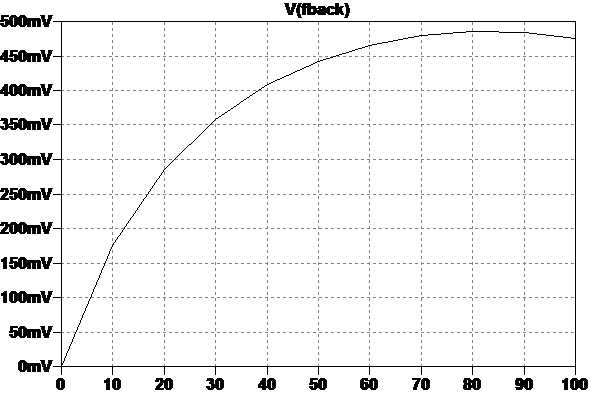
The plot to the left from an LTSPice sim shows how the amount of feedback changes over the DELAY TIME pot position (which is along the bottom 0 - 100%). I've used a 1 Volt signal in this sim, so the vertical axis shows mV. When delay time is minimum (84msecs) we have 0 = no repeats, so we get just one quick slapback echo. When delay time is maximum (around 600msecs) we get about 500mV which means 50% of the output is fed back, so we will get multiple repeats which die out. On my Blackstar Fly 3 I can hear about 3 repeats on max delay setting.
You can see from the graph that it's not linear, there is a big increase in repeats as delay starts to get longer, then it flattens out a bit for the last 30% of the pot travel.
It's a neat combination of delay time and feedback level which turns out to be very natural. You don't want multiple repeats at very short delay times else you'll end up with nasty "bathroom reverb". But you do want multiple repeats on long delay settings so you can get nice echo trails and cross-rhythmic effects.
Interlude #2: Thanks for all the fish thanks !!!!
Before going further I just want to say Thanks for the messages of "Thanks" that some people have sent me for doing this breakdown of the Fly.
I have also answered one or two technical queries that people had about this amp as best I can, from what I know so far.
Once I've traced and documented the whole thing I'll be able to give more certain answers to questions about possible mods, and power supply alternatives.
EQ section
So tracing this section was a real pain. Analog circuits are not easy to trace because drawing a meaningful schematic often relies on recognising the circuit from previous experience. Its like listening to a guitarist playing and saying "I know that lick/riff/chord progression - I've heard that before on a track by ...." and so you know what it is. But if someone just handed you the notes down on a blank sheet of paper "A G B Eb ..." with no rhythm and no context and said "where's that chord sequence from" you'd probably struggle or end up guessing wrong. So it goes with analog circuits. It's one thing to say that R23 is connected to that C14, but it's another to say what the circuit is meant to do and draw it in a sensible way.
Case in point the Blackstar Fly EQ section - lots of R's and C's in this one.
The post-EQ filters
Aren't audio filters the same as EQ? Basically, well, yes. I just couldn't thnk of a better name for this bit of the circuit. I've called it post-EQ because I've already noticed there is another EQ circuit (the famous ISF feature) which we'll come to in the next bit after this.
The part of the main board in the Fly 3 which contains the EQ circuit is shown in the photo on the right. You'll notice I've ripped the Upper Deck board off as it was getting in the way constantly. In fact the ribbon broke off as I was repeatedly moving it around to probe componennts etc. I'll fix this back later when I'm done.
I started tracing back from the input to the Mixer and Headphone Amp (see section 6.1) and as I expected came straight to the master VOLUME pot, VR3. This controls the level from the pre-amp into the mixer which drives the headphones and the Class-D speaker amp. It also controls the level into the Tape Delay circuit (see section 6.2).
The input to this pot comes from the EQ section and the first thing I hit (working backwards) was a signal chain made up of 2 halves of an op-amp IC3. IC3 has the markings "TI 2272C 4BM 6K6E". Again, TI = Texas Instruments, the manufacturer of the IC, and a quick Google confirms TVM2272 is a dual, low-noise, op-amp. Here is the datasheet link: https://www.ti.com/product/TLC2272
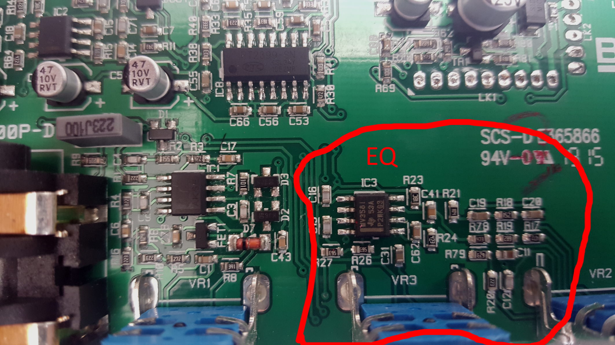
Blackstar Fly 3 main board EQ section
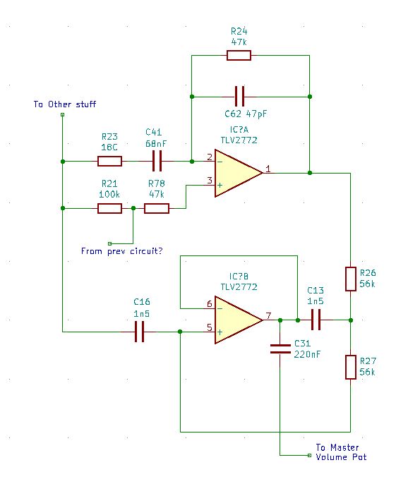
Now you know what I was saying about tracing analog circuits being a pain in the ***. Especially when they are surface mount analog circuits with PCB board traces disappearing under SMD components. Well to illustrate this, here (on left) is the circuit I got first time around from tracing the components connected to these 2 op-amps.
This circuit looks quite nice, but as I drew it out I was thinking "what is this?" At first I thought the bottom op-amp was some kind of Gyrator circuit (yep sounds like a weapon Bond might use but a Gyrator is a real circuit which turns capacitors into inductors - anyway its not a Gyrator, it's more boring than that). Also is the input signal - labelled "From prev circuit?" really going to 2 resistors which go off in different directions?
The only things which looked a bit familiar to me were:
1. The top IC has an R and C in parallel from "-" input pin 2 to output pin 1, which is a normal type of amplifier stage
2. The bottom op-amp has "-" input pin 6 connected directly to output pin 7 which forms what is called a non-inverting buffer, which is a fancy name for a gain stage with no gain (i.e. voltage gain of 1)
And the "other stuff" label had me puzzled - I've tried to trace it but it goes off everywhere - to other ICs and to lots of other Rs and Cs. Not very helpful.
Here's another thing about surface mount boards. Do you see R23? It has a marked value of 18C. That's what's written on it. What does that mean? Well because SMD components are very small, sometimes the manufacturers can't fit the full value on. So they use a code instead - see this handy resistor code-breaker table
Back to the EQ circuit. The clue in fact was guessing that the "other stuff" was most likely a mid-rail virtual ground. A what?? It means something which looks to the op-amps like its signal ground but in fact it is at a DC voltage above ground (often half the supply). This is very common in circuits with op-amps and is because op-amps dont (usually) like having input voltages that swing positive and negative when they only have a positive supply rail. Its like expecting a door in your house to swing both outwards and inwards - in fact it can only (unless you have a proper swing door) swing in one direction.
Lots of designs have this mid-voltage rail. They make it look like the signal swings positive and negative around the mid voltage. Its like setting your door half open. Then you can swing it backwards and forwards (as long as you don't hit the frame).
With that hunch about the virtual ground mid-rail) I re-drew the schematic and got something a lot more familiar looking (see below).
Now we're getting somewhere. This is 2 filters, one after the other. The signal flow is left to right. I've added the VOLUME pot too.
The first filter stage around IC3a is a gain stage with frequency shaping. I've seen this type of filter in a slightly different configuaration, where R23 would get the input signal, and pin 3 (+ or non-inverting input) is tied to ground. My guess is Blackstar have flipped it this way because the input impedance at pin 3 (non-inverting input) is very high (like megohms) so whatever drives it won't be affected.
It's not so obvious to work out the response of this type of filter since the gain is set by the way C41 and C62 change resistance (impedance is the technical term) over audio frequencies. R23 and R24 ensure the circuit is stable at all freqeuncies and will set a gain on this stage. To understand a circuit like this at a simple level all you really need to know is that capacitors have less resistance at higher frequencies. I'll SPICE it later to see what the actual response curve is.
Then we have the second filter using IC3b. This is common circuit known in the trade as a Sallen and Key filter. This one is definitely low-pass so it rolls-off highs.
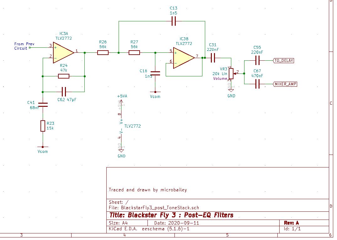
It's much easier to work out the response of this circuit without SPICE, espescially since R26=R27 and C16=C13. In fact we can use the same calculator as this http://www.muzique.com/schem/filter.htm from the guys at AMZFX (there's loads of other calculators on the web). Plugging in the values we get 1.8kHz So this second filter starts to attenuate everything above 1.8kHz fairly quickly. Given its always in the signal path I wouldn't expect the Blackstar Fly 3 to be very good with high piched signals (from a keyboard or a shut-out cat for example).
Post-EQ filter frequency curves
Let's run some SPICE simulation on the post-EQ filters and see what curves we get. I'll simulate each post-EQ filter stage and then the whole thing (IC3a, IC3b, and the VOLUME pot) just to see what it does to the signal. Using a dummy 1V sine wave input in the SPICE (I've used LTSpice again) I get the curves shown below:
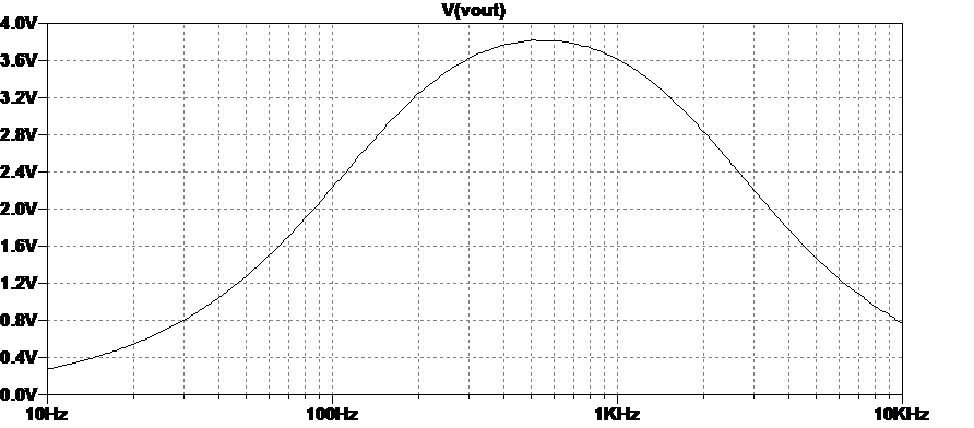
Here's the plot for the 1st filter stage made from IC3a, C41, R23, C62, and R24.
As you can see it's a high-pass, starting to level off around 400Hz.
It's also got a fair bit of gain - our 1V signal comes out at 4V once the filter stops attenuating. So the voltage gain is around 4 (if you're interested it's set by R23 and R24 ratio).
By the way - this isn't the way we would normally show a filter plot. It's normally shown in dB (decibels). But I've shown it as voltages here just to keep things easier to understand. Bear in mind though that since we hear sound much more the way decibel scale works, the dB plot would look more like what you hear (if that makes sense!).
Ok let's do filter stage 2 next.
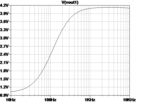
Here's the plot for the 2nd filter stage made from IC3b, R26, R27, C13, and C16.
As you can see it's a low-pass, starting to drop off around 700Hz.
This filter has no gain, in other words what goes in comes out but attenuated by the filter itself.
So can you guess what we get if we put both filters one after the other? One boosts higher frequencies and the other chops off low frequencies.
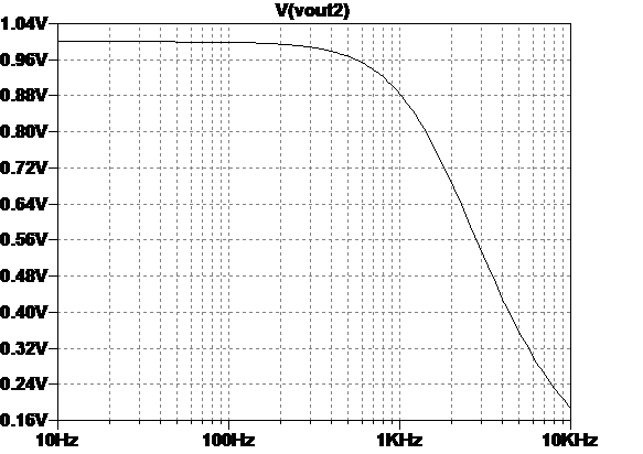
Yes that's right - we get a bandpass filter.
I've included the output cap C31 and VOLUME pot VR3 in this SPICE too.
Frequencies between about 150Hz and 2kHz pass through nicely, and out side of that stuff gets progressively attenuated. The highest note on a standard guitar in standard tuning is around 1.3kHz so none of this is very unexpected.
However this re-balancing of frequencies is part of what gives the Blackstar Fly 3 its voice. The voicing is also dicated by the speaker repsonse (which I'm guessing does not go very low) and the ISF tone thing which precedes these filters.
This plot looks like it shows a huge hump in the middle. Actually its flatter in the middle than that. Again if I'd done it as dB scale the hump would not look so pronounced. And that's what you hear.
The ISF tone circuit
Finally I got round to writing up this circuit! (long story - laptop broke, laptop got repaired, laptop immediately broke again, laptop now all good).
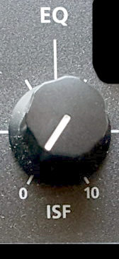
So Blackstar have this Patented EQ feature, almost from when they started, called ISF "Infinite Shape Feature" . It's on pretty much all of their amps, including the Fly.3 According to Blackstar's website "the ISF control is continuously variable between all the traditional responses allowing you to effectively design your own sound" and the marketing picture shows a nice picture of a NYC taxi cab on the left (counter-clockwise) of the ISF knob and a London taxi cab on the right (clockwise) of the knob. If we know our amps I think we can start to see what the implication is.
Turn the ISF knob CCW and it sounds American and turn it CW and it sounds British (or Pommie if you come from the Land Down Under).
I've got to say that on the Fly3 with a tiny speaker that's kinda not so obvious, but it still does have an effect on the tone. You'll see forums where people argue about which way the ISF sounds best.
As a quick aside, I find it interesting that people always push this ISF know either all the way to 0 or all the way to 10. Blackstar could have saved money and just used a switch! But then it wouldn't seem so much of a selling point would it.
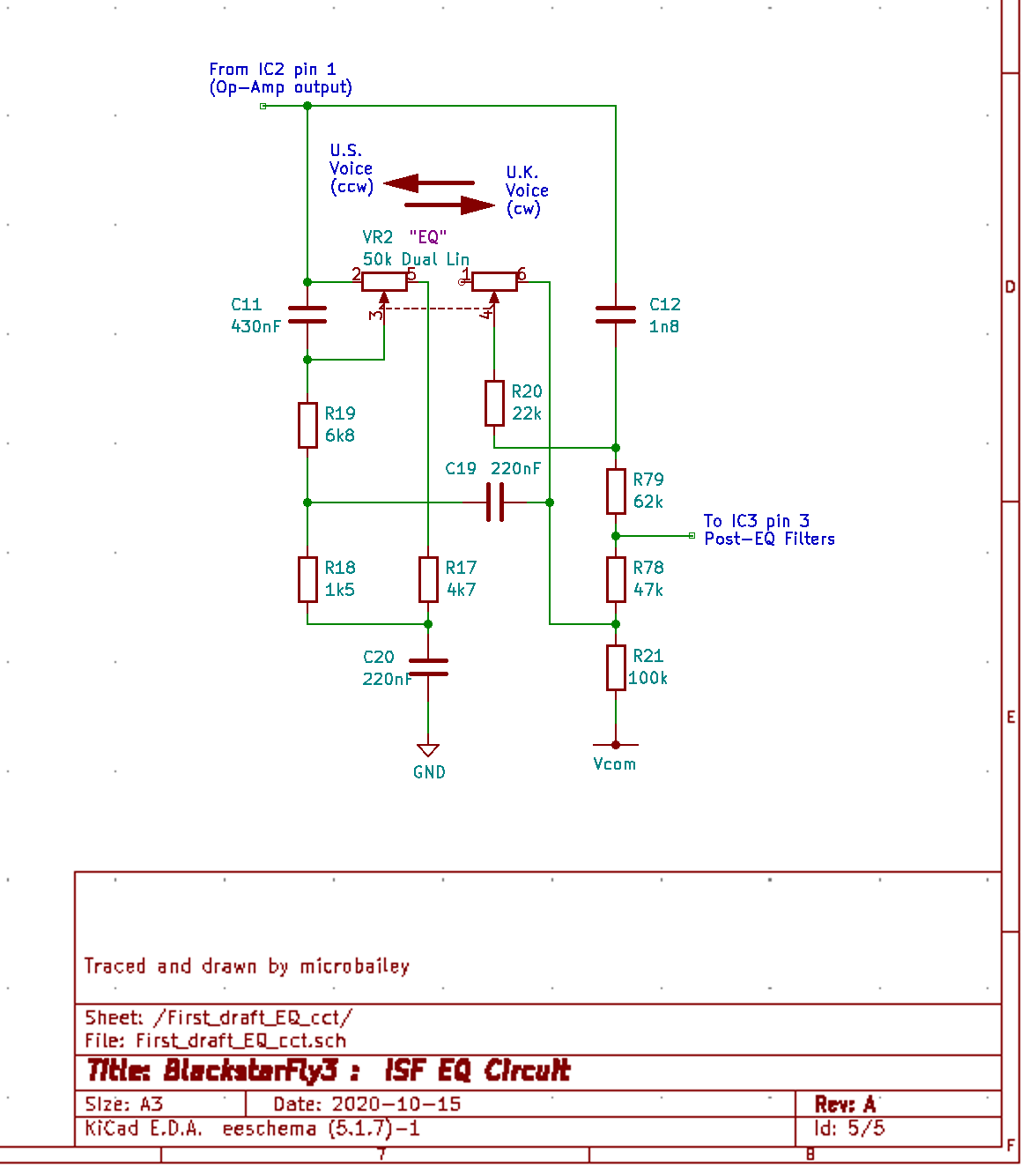
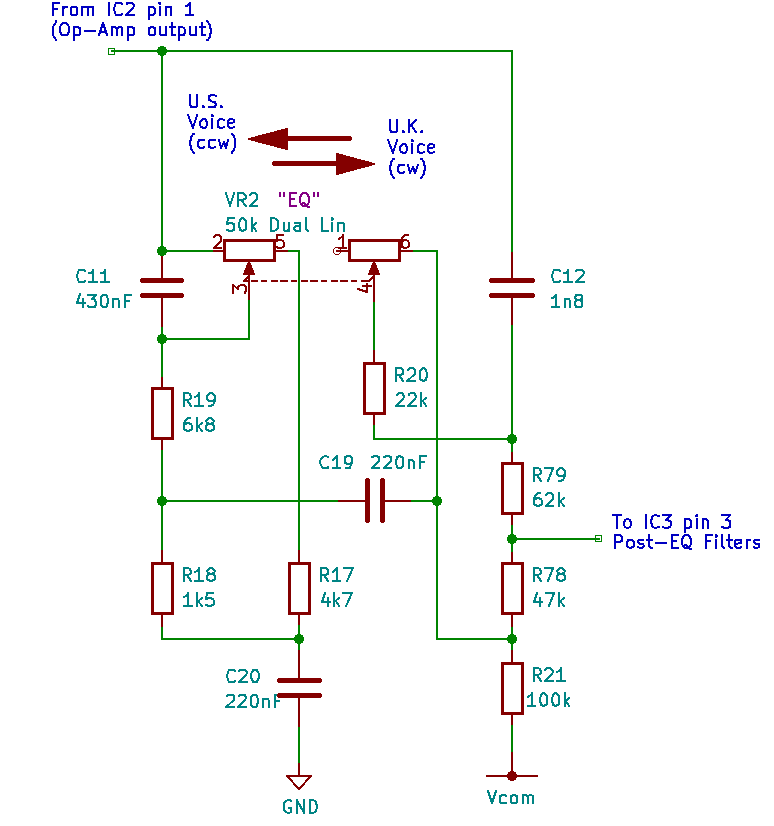
So on to the circuit, which I traced and I've shown on the left. This feeds directly into IC3 pin 3 (opamp +ve input) on the Post-EQ filters (stage 1).
The pot is dual-ganged like the one used for the Delay circuit. So both pots change together. The dotted line in the schematic symbol I've used shows that.
At first sight the circuit looks unfamiliar, but in fact, if you are used to looking at Tone Stacks (the name for network of Rs and Cs which do the EQ) on classic Fender and Marshall tube amps it is not so far away.
To understand this circuit I dug out Blackstar's ISF patent which was filed the year before they launched the Series One amps. The patent is publically available on the UK Government website via this link: British Patent GB-2446188
I'm playing safe (I don't particularly want to go to jail) so I suggest you read it rather tha I copy it to here. It quite clearly explains the idea and gives the original ISF circuitry proposed by one of Blackstar's founders.
Blackstar's basic idea was to have a movable notch in the frequency response, created by coupling a variable RC low pass filter and a variable RC high pass filter with cutoff frequencies spaced apart, which track each other. They do this by using a dual-gang pot. There's a little bit more to it - they add a high frequency bleed cap (labelled C1 in the patent doc) around the low pass filter pot (bleed cap is a term for a capacitor which allows some signal to bypass something else, usually a resistor or pot - standard on guitars and amps) This bleed cap gives a boost to higher freqeuncies as the pot goes CW. Anyway the idea is pretty simple (as a lot of patents are - I should know - I've filed some and they were pretty simple too).
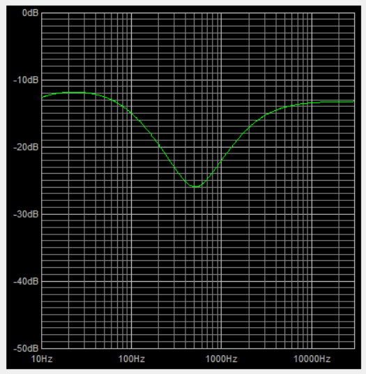
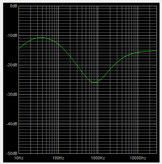
To understand what this has to do with America and Britain we need to look at what classic US and UK amp tone stacks do to guitar frequencies. Take a look below at the frequency response for a classic Fender and classic Marshall tonestack, with all EQ controls at 12 o'clock. These plots came from the excellent free Duncan's tone stack calculator. I highly recommend it to play with to learn about different amps and their tone stack filter circuits.
Blackstar Fly3 ISF circuit
Classic Fender amp tone stack response
Classic Vox amp tone stack response
The first thing you notice are the big dips. In the Fender response it's around 500Hz which accounts for the legendary Blackface scooped tone. If you look closely you see the Vox's dip is around 850Hz.
Marshall amps (not shown) have a similar dip (not as deep) dip around 700Hz and also have more top end boost.
So my guess is Blackstar thought 'why don't we make an EQ knob which can move the dip around to give a US sound at one end and a UK sound at the other'. Moving this dip (freqeuncy notch) is one of the things which shapes an amp's tone as you'll see if you read the ISF patent.
Infite Shape Feature circuit analysis
If you look at the Blackstar ISF Patent Application circuit on the front page, you will see Blackstar proposed a circuit which still has Bass, Mid, and Treble EQ pots along with the ISF dual-gang pots which they call Sweep in the patent. This is the EQ knob configuration on the big Blackstar amps.
In the Fly3 circuit (shown here again), you can see they replaced the Bass pot with fixed R21. They replaced the Treble pot with fixed R79 + R78. They replaced the Mid pot with R18 + R19. And they slightly altered the second pot in VR2 (open on one end) but it still works as a variable resistor rather than a pot. Other than that it is the full EQ circuit but without the ability to vary the Bass, Mid, Treble. Again I would guess they used some 'golden ears' to decide the best sounding settings for these pots and then just replaced them with fixed value resistors.
The simplest way to view the EQ circuit is that the LP filter is made up from VR2a+R17 and C20, while the HP filter is made up from C12 and VR2b+R20. The rest of the components either limit the range of the filters, combine their outputs, or add some extra shape to the freqeuncy response. CCW (U.S.) moves both LP and HP filter cutoff frequencies lower, and CW (U.K.) moves them higher. C11 is the bleed cap adding some higher freequency boost when VR2 moves toward U.K. sound.
I'd say if you wanted to change the tone of your Blackstar Fly3, these components are a good place to start. Only thing is everything in this type of circuit interacts so if you change one value everything shift's around a bit.
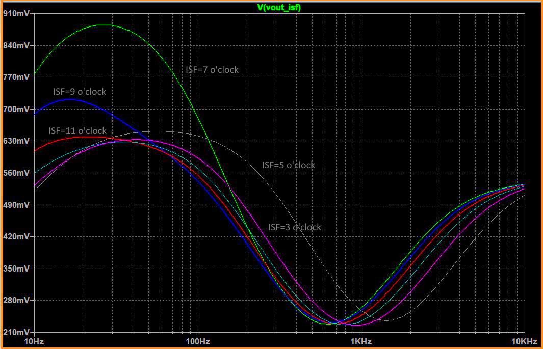
ISF frequency curves
Again I ran SPICE simulation on the ISF circuit, with the EQ knob at various o'clocks to see what curves we get. Using a dummy 1V sine wave input to LTSpice I get the curves shown below:
Let's explain a bit here.
I ran 6 sims and I've shown them overlaid.
The green 7 o'clock position is ISF hard CCW which is the U.S. tone setting. You can see its notch is the most to the left, around 600Hz. Also there is a pronounced boost around 30Hz. Not sure why since the speaker will not be able to reproduce that.
The grey 5 o'clock position is ISF hard CW which is the U.K. tone setting. You can see it's notch is the most to the right, over 1kHz.
The red 11 o'clock is around the middle.
Blackstar Fly3 ISF SPICE curves
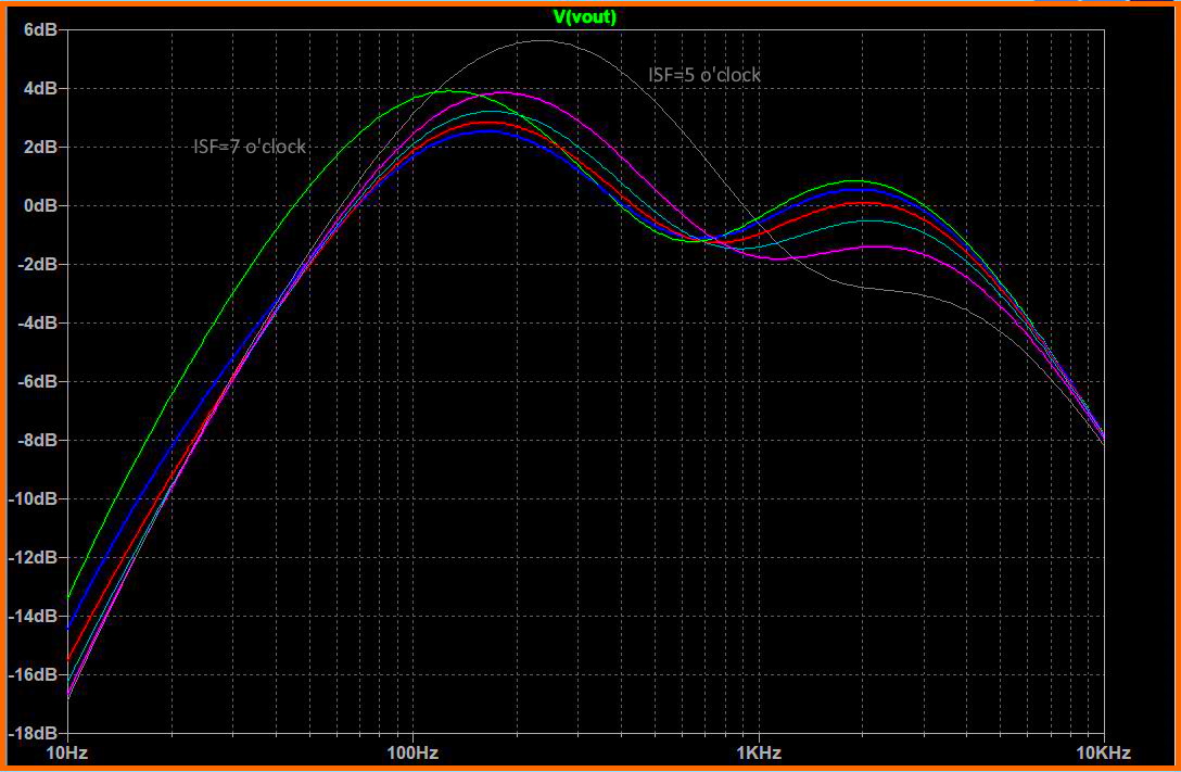
And here is the same again but with the ISF circuit AND the post-EQ filters we looked at earlier. Note I changed to dB scale so it compares better with the earlier curves from the Duncan Tone Stack Simulator.
Same 6 sims with the same knob positions.
Now it looks like the U.K 5 o'clock setting (grey) has a hump around 300Hz.
Of course the speaker voicing will affect all of this, but at least I now get an idea of how this amp's EQ works.
And now hold onto your seats - while tracing the PCB I found what looks like another interesting filter circuit (using an op-amp) before the ISF circuit!
Blackstar Fly3 ISF and post-EQ SPICE curves
Pre-EQ filter circuit
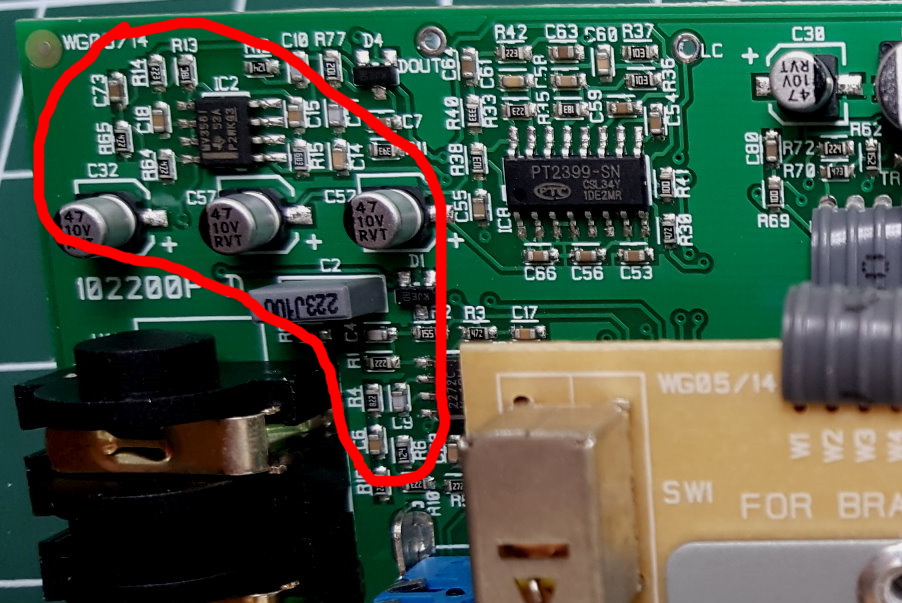
Well as I said - just as I thought I was nearly finished - I find some more filters ! (there's more filters in this thing than on a celeb's Instagram post). This time we're in the top-left hand corner of the Main PCB (see photo) around IC2, another 385 dual op-amp.
At first the circuit didn't look particularly interesting - just another standard amplifier sstage with some EQ built-in, but then the tracing turned a bit strange. when I found one of the 2 op-amps with what looked like inputs but no output connection.
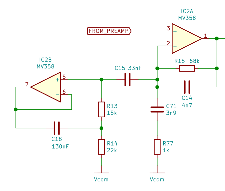
Blackstar Fly3 pre EQ filter circuit
I've shown the circuit I traced on the left. IC2A (one half of the dual MV358 op-amp) is a non-inverting (what comes out is in same general phase as what went in) audio pre-amplifier. In this type of circuit the gain is set by the ratio of the total 'resistance' between pins 1 and 2 to the total 'resistance' between pin 2 and the common (labelled Vcom in my schematic). The reason i put the word resistance in ' ' quote marks is because its not really called resistance. Because the total is made up of a resistor and a capacitor (e.g. R15 and C14) it's what we call impedance. Anyway, just think of it as resistance which depends on the frequency (the C has different 'resistance' at different frequencies - lower R at higher f).
This makes the amplifier around IC2A into yet another filter. If you've being paying attention you'll recognise this circuit as the exact same one they used after the ISF tone stack in IC3A (see the Post-EQ Filter section).
However this filter has another iodd bit attached. What is the circuit on the left-hand side of C15 doing? It looks like an amplifier stage that goes nowhere (pin 7 doesn't feed any next gain stage or output). At first this confused me, but then - as I said somewhere earlier - once I re-drew the circuit it started to look like something familiar.
It's what's called an Active Inductor circuit.
Interlude: Active Inductors, Gyrators, and Black Holes
I got quite excited earlier when I thought I'd found a Gyrator circuit in the Fly3 (I don't get out much you see). Anyway, it turned out not to be. However now I've found an Active Inductor which is almost just as exciting.
Active Inductors sound like sinister operatives from a dystopian world, but in fact they are quite friendly. They take a capacitor (in this case C18) and make it 'look' to the outside world like an inductor. In case you're not too sure what an inductor is, it's traditionally a coil of wire wound around something magnetic (schematic symbol looks like a coily line). And there's the problem - if you want an inductor in your circuit they tend to be quite big (unless its a tiny inductance value). Take a look inside an old valve (tube) amp. What do you see? Vacuum tubes of course, and years of accumulated **** . You also see big chunky tubes with a wire poking out of each end. The bigger ones are likely to be inductors (they also used to be called chokes in prehistoric times). Imagine trying to mount one of them on a surface mount PCB like the one in the Baclstar Fly3.
It's much easier to use a tiny surface mount op-amp, 2 resistors, and a tiny capacitor to do the same thiing as a giant inductor. That circuit is called an Active Inductor or (and this is a variant of it) a Gyrator. The reaon they are exciting is that they are sort of magic and seem to defy the rules of physics. There's a great article about Gyrators here on Hackaday which even warns you not to Google "Gyrator Video" at work. Gyrators are sort of like Black Holes which bend the electrical waves in strange ways.
There's another good article on the Elliot Sound products website pages if you wat more detail. - you will see this exact circuit shown there.
If you wonder why you want an inductor for audio, its because an inductor (symbol L) with a capacitor makes a great boost/cut filter for a particular frequency. Original Graphic Equalizers used to be packed with inductors, but now they tend to use Gyrators made with op-amps and caps.
Pre-EQ filter analysis
So we got an Active Inductor made out of IC2B, R13, R14, and C18. Using the textbook formula (R13 x R14 x C18) I calculate it is equivalent to a 43H (H is for Henry) inductor. That would be a lot of coils of wire. In series with C15 it forms a classic notch filter with a frequency set by the C and the equivalent L value. However in this case that notch circuit is in series again with C71 + R77 so it should create a cut in feedback which equals a boost in the gain at that frequency. It's time for some more SPICE to see what the overall frequency response curve for this circuit around IC3 is.
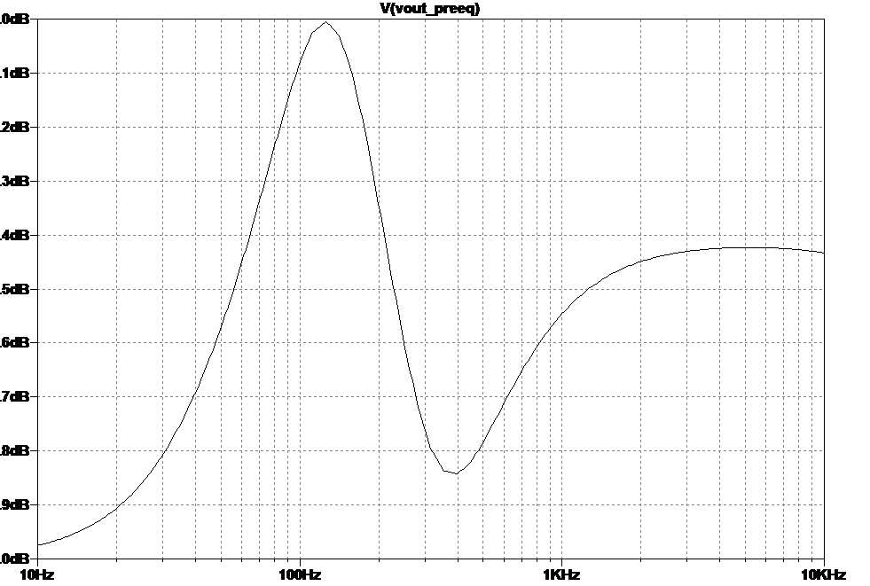
Blackstar Fly3 pre-EQ Spice simulation
Here's the frequency-gain plot which I get from simulating the pre-EQ circuit in LTSpice.
And as predicted there is a huge gain hump. It's just above 100Hz followed by a big dip around 400Hz. Above 2kHz the gain flattens out. The scale here is in dB (decibels) so these gain boosts and cuts are pretty big.
That active filter of 43H virtual inductance in series with a 33nF cap (C15) works out (online calculator http://circuitcalculator.com/lcfilter.htm ) at a frequency of 133Hz, so that all sounds about right for where the peak is.
It's clear this pre-EQ circuit has a big part to play in the Fly3's tonal character. bmxguitarsbmx of https://www.freestompboxes.org/index.php suggested that this low frequency boost might be Blackstar's attempt to model the low end resonance of a large speaker cabinet.
Don't forget that this filter is part of the overall frequency response of the chain of ISF tone stack and post-EQ filters, and of course the Blackstar Fly3's speaker cab itself (I don't have a simulation for that I'm afraid, but more on the speaker later).
So here is the Spice plot for the post-EQ + ISF tone-stack + post-EQ, in other words the whole caboodle (although I've still got more pre-amp circuit to trace!)
Now we can see there is still a pronounced boost around 130Hz thanks to the pore-EQ circuit. Also we see the hard clockwise (5 o'clock) setting of the ISF knob, i.e. 'UK' setting, seems to make the most difference to the EQ, boosting the mid frequencies. At 'US' setting (7 o'clock) we get more of a boost around 2kHz.
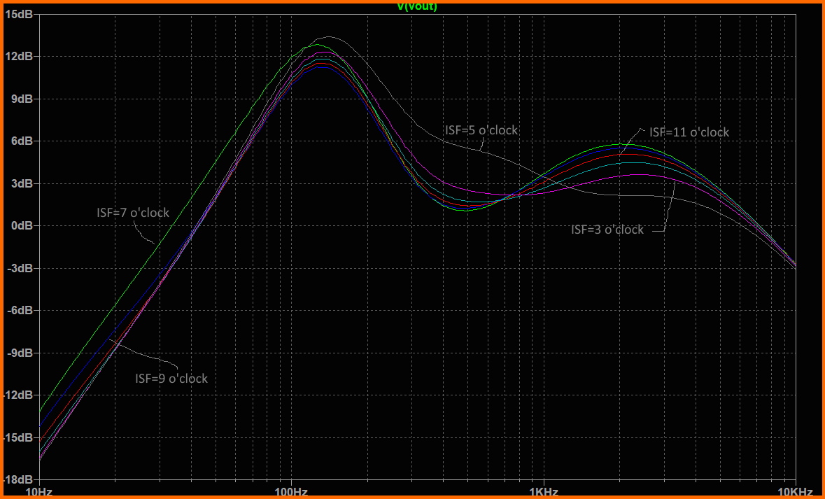
Blackstar Fly3 pre-EQ, ISF tone-stack, and post-EQ curves from Spice
Full EQ circuit
Overall I'm kiinda surpirsed Balckstar went to all this trouble. There's three filter stages here. Credit to their engineers and management that they didn't just go for a generic 'tone knob' which would have had lower component count and would have been cheaper to manufacture.
Here is the full schematic for the EQ stage:
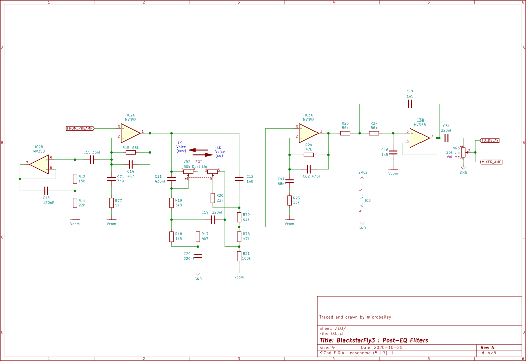
Blackstar Fly3 Full EQ section (pre-EQ, ISF tone-stack, post-EQ) schematic
Pre-amp and Gain Stage
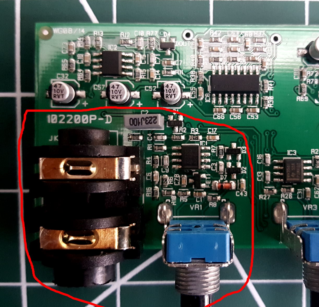
Main board preamp section
I'm getting near the end of this now (which is actually the beginning of the amp). Feeding signal to the EQ is the pre-amp which takes the raw guitar signal and amplifies it ready for the EQ etc. This also includes the gain stage which as we'll see handles the overdrive effect (activated by the "OD" switch on the front panel).
Looking at the Fly's Main Board shown here, the pre-amp is the bunch of components close to the input jack (I've drawn a red box around them). In fact they're the only components I haven't looked at yet, apart from the power supply circuit (still to come). the circuit is built around IC1 which has the markings 2272C with a "TI" logo. We've seen TI before (Texas Instruments) and this part 2272 is a dual op-amp again (datasheet here) so I'm expecting 2 stages in the circuit.
Looking at the PCB in this area I can see several diodes (which suggest clipping to me), and a tranny marked FET1 (they actually tell you its a FET!) I'm wondering of this FEt has anything to do with the clipping?
So I got my LCR meter and traced out the circuit for the pre-amp and yes there is clipping (using those diodes) and a bit more EQ (again). Here is the full circuit for the pre-amp and gain stage.
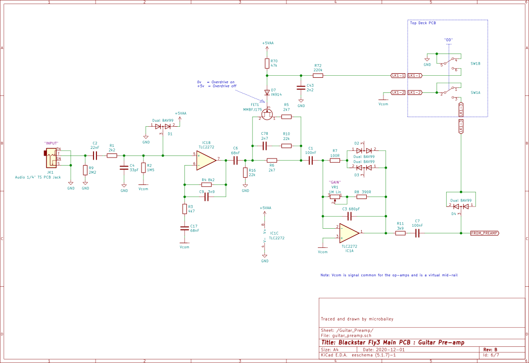
Blackstar Fly3 schematic for preamp and gain stage
Pre-amp first stage circuit analysis
The guitar signal cmes in through the INPUT jack (which is shorted to ground when nothing is plugged in to prevent hum pickup) and feeds an initial preamp stage around IC1B. On pin 5 (the op-amp input) there are 2 diodes (D1) between the input signal and the power rails (GND or 0V, and +5VA). This is a commonly used way to protect the op-amp input from a voltage which is above the highest, or below the lowest voltage inside its little package. Its a bit like a lightning conductor on your TV aerial - when the lightning strikes it goes through the conductor and not (hopefully) though your living room. In this case any excess voltage causes a current through the diode not the op-amp. Btw - these 2 diodes-in-series-in-1-package are very handy for, well, when you want 2 diodes! They take up less space than 2 diode packages and also the diodes are well matched (meaning they behave almost exactly the same as each other).
I've labelled a rail Vcom (short name for Vcommon) that quite a few of the components connect to. As I think I mentioned with the EQ circuit, its normal in a guitar pedal to have a 'vrtual ground' which in effect is a half-way voltage which the signal gets referenced to. Op-amps much prefer their inputs and output to swing around something in the middle rather than at one extreme.
IC1B is at the heart of another low pass filter formed with R3, C17, R4, C9. We've seen these filters before in the Tape Delay circuit - Blackstar designers seem to like them. I've plotted (using LTSPICE) the behaviour of this filter the the Rs and Cs straight after it) on the right here. Its a broad bandpass letting approx 100Hz upward through, with a peak at 2kHz. This gentle upper boost might be for the circuit which follows.
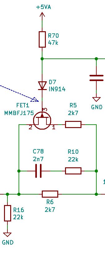
Then we get to the circuit around C70, R10, R5, R6. I had wondered if FET1 had anything to do with clipping (more on clipping later) but the the traced circuit shows the answer is no. When a FET (which stands for Field Effect Transistor, one of the types of transistor) is connected the way this one is, it is just a voltage operated switch. The GATE pin (the one with a small arrow on it) is the control for the switch. When it's at a voltage higher than the other 2 pins (which btw are called SOURCE and DRAIN) the switch is 'open' so no signal passes. When the voltage is around the same as the other 2 pins then the switch is 'closed' meaning signal passes. In this circuit the diode D7 allows FET1 gate to 'float' around the same voltage as the other 2 pins when the control input (junction of C43 / R72) is at 0v. The components C43 and R72 ensure that changes in the control voltage don't happen instantly which would cause an audio pop.
You can see that the switch SW1B (SW1 is on the Top Deck Board) controls whether FET1 is 'open' or 'closed'. When OVERDRIVE is engaged (SW1 pushed in) the FET1 is 'closed' and when it isn't, FET1 is 'open'. FET1 closed means R5 shunts across R6, and as you might remember from school physics classes (if you were awake) 2 equal resistors in parallel give half the resistance, in this case 2k7/2 = 1k35. The reason that is important is that the 2k7 or 1k35 value directly affects the gain of the next preamp stage around IC1A. In summary, when the OD switch is pressed the gain doubles: or to put it another way, engaging overdrive gives more gain - no surprise there really is there?
Finally on this part of the circuit, C78 and R10 act to put yet another resistor (22k) in parallel with the 2k7 or 1k35 at higher frequencies and so give even more gain at the top end - yes another filter!! I included this filter in my LTSPICE frequency plot above.
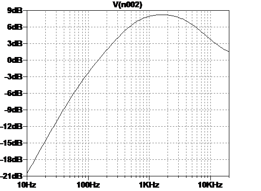
Pre-amp stage 1 filter frequency plot
Due to this page being too long and breaking the internet this Blackstar Fly3 Teardown is continued on another page innovatively called Part 2