Blackstar Fly 3 guitar practice amp teardown (Part 2)
Part 1 ran out of webpage so we continue as Part 2 ...
The Fly 3 from Blackstar is a great little 3W guitar practice amp. It easily beats similar sized amps by competitors for volume and clarity.
Here is the description from the makers www.blackstaramps.com/uk/products/fly-3
Although it looks a bit like a toy it is actually a very well made amp which is ideal for bedroom guitarist use, silent practice with
headphones, or even busking.
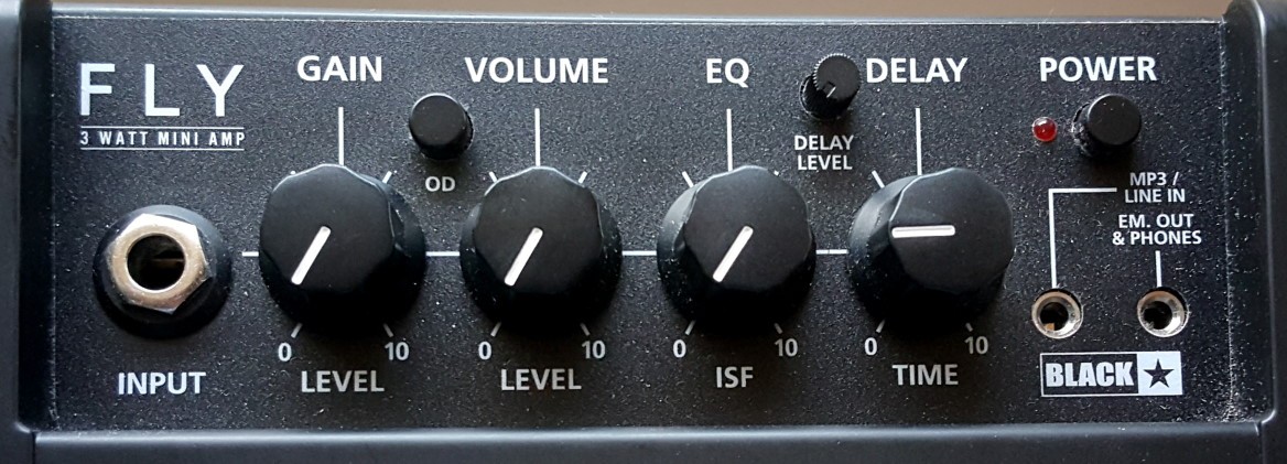
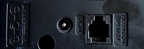
So what are its secrets? Why is it so loud and so clear for a small battery powered amp? How does it do the "Tape Delay"? What does the (optional) extension cabinet actually do?
There's very little explanation of how this amp works on the web, and I couldn't find any schematics (circuit diagrams).
So I decided to take one apart to see what's inside. This is Part 2 of the Teardown.
This follows on from Part 1 If you haven't read that first it might be a good place to start!
Overdrive circuit analysis
Next up is the overdrive gain stage. Ignore all the diodes for now (pretend they're not there) and you get a classic inverting op-amp circuit with the gain set by (VR1 + R8) / Rpin2 where I'm calling Rpin2 the total parallel value of R5, R6, and R10. As said before, when OD is pushed and FET1 is 'closed' we get a smaller resistance in total and so the gain goes up. The overall gain, whether we are in OD mode or not is set by the GAIN pot VR1. No prizes for working out that the more we go clockwise the higher the gain gets - and it can get pretty high thanks to VR1 being a 1M pot and R5||R6||R10 being just a few kohms. 1,000,000 / few 1000s = a lot!
Except it can't go anywhere near a voltage gain of x500 because we always have D2 and D3 adding negative feedback from the op-amp output back to pin2 input. This limits the gain when the diodes kick in. The diodes do what's called clipping on the signal. D2 and D3 are those crazy serial diode pairs again, so they actually act more like a "super-diode" (I just made that term up).
Interlude: What is clipping?
So what do you think of when you hear the word clipping? Hedge? Toenails? Moustache? (maybe that last one is trimming?). Anyway they all have something in common: clipping involves taking something off, usually at the extremities. Audio clipping involves taking something off at the far ends too, in this case the ends of the audio waveform.
Let's think of it like this: Imagine bouncing on a trampoline in your garden - that's like an audio signal going up and down every cycle. Now imagine doing the same thing in your house. There's a problem: you're gonna hit the ceiling with your head (unless you live in a mansion with 18ft ceilings). How far you can go up is limited by the ceiling. That's basically what clipping does - it stops the audio waveform reaching it's peak and holds it at a fixed voltage level until it comes back down. Don't confuse this with audio limiting (although there are a lot of similarities) which limits the envelope of the audio signal (in other words how loud it is).
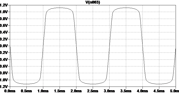
Example of soft clipping a sine wave
You'll see the terms hard and soft clipping.
- Hard clipping is a concrete ceiling - ouch!!
- Soft clipping is a rubber ceiling - you still hit it but your bounce get's curtailed more gradually
There's a nice bit of soft clipping shown in the simulation here.
You'll also see the term diode clipping. This just means using diodes to stop the waveform going to its max or min voltage. This works because all diodes only conduct when there is enough voltage across them.
How much voltage is enough? Glad you asked that - see the table on the right.

Diode types and their turn on voltages
That's the easy bit about clipping out of the way. The harder part to explain is how and why it affects the tone of the clipped audio.
Simply put, clipping audio generates (and beefs up) harmonics. Harmonics are like extra 'notes' higher in frequency than the basic note (called the fundamental). The more harmonics in a sound, the more character it has. This website has a nice comparison of sounds. The steeper the waveform changes, the more harmonics it has, and the 'harder' it sounds. The maths behind all this is very complex so let's skip all that and just say this:
- Hard clipping gives an abrupt change to the waveshape and makes audio sound harsher
- Soft clipping gives a smoother change to the waveshape and audio sounds rich but less harsh
Now all this matters because a long time ago guitarists (and then organists - no prejudice on this site) found that when they wound up their amp volume, and the audio started to clip, they got a grittier sound with more character. When valves (vacuum tubes) get to a point where they are amplifying flat out (technical term here is cookin') they generally soft clip the waves and give a nice character to the sound. Transistors can be made to do this too but its not so natural for them. Clipping gets built into guitar amps (like our Blackstar FLy3) because it mimics what a tube amp would do when really pushed (except with the 3W Blackstar Fly your ears are not flattened when the amp is clipping).
There's a lot to say (and others have said it - just search the web) about clipping e.g. hard clipping for guitar fuzz, assymetric clipping tone, clipping vs. non-linearity etc etc, but at least this overview gives some basics to understand the Fly3.
Clipping gain stage circuit analysis
To remind ourselves of the clipping stage here is the pre-amp schematic again, with the clipping part zoomed in.
So it seems Blackstar wanted to have soft clipping come into play when the "clean" signal pushed the amp input hard, and then add more agressive hard clipping when the overdrive effect is engaged. I can't help notice this circuit looks like the clipping stage in the classic Ibanez Tube Screamer pedal - just compare it with the circuit in 1.4 of https://www.electrosmash.com/tube-screamer-analysis (the excellent ElectroSmash circuit analysis of the most copied pedal circuit ever). If you look at section 6 of https://www.electrosmash.com/boss-ds1-analysis (another ElectroSmash circuit analysis) you'll see how the Fly circuit uses the exact same hard clipping arrangement as the Boss DS1 pedal. In summary we could say in essence that the Fly Overdrive stage is a Tube Screamer followed by a DS1 distortion. Both of these are classic distortion pedals so there is a good heritage here. And no FET clipping in sight anywhere after all!
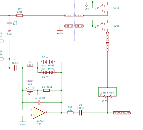
Blackstar Fly3 clipping circuit
As said earlier, D2 and D3 limit the excursions of the voltage at the output of IC1A. Since there are 2 in series in the package, and they are silicon diodes, the overall 'turn-on' voltage forthe pair is around 2 x 0.7v = 1.4v, and since D2 faces one way and D3 the other, the clipping at 1.2v is symmetrical (both ups and down get clipped equally).
For this kind of op-amp circuit we assume pin 2 and pin 3 are always at the same voltage, and so the output signal voltage also appears from IC1 pin 1 to pin 2. As this voltage rises D2 and D3 start to conduct. The important thing here is that diodes don't suddenly switch on - they don't 'fire'. They gradually conduct. This gives soft-clipping.
I can see that there is no switch for D2 and D3. They are always connected in the circuit. So this pre-amp stage will always soft-clip if driven hard enough, whether the OD button is pushed or not. As the GAIN VR1 is increased, the guitar signal will be more amplified and eventually will start to clip. Plug in a Les Paul, turn up the amp GAIN with OD off and you'll be able to hear that clipping.
C3 provides some low pass filtering on this gain stage and is perhaps there to roll-off the upper harmonics from any clipping (remember clipping creates lots of new harmonics).
What IS switched when OD switch SW1 (on the Upper Deck board) is engaged is the diode pair D4. These clip the signal again by clamping the peaks to 1 x 0.7v = 0.7v in each direction. This is more agressive than the 1.4v soft clipping around IC1A and will give much more noticable distortion, as well as reducing the signal voltage into the next stage. This is hard clipping.
So much of the character of any amp distortion is governed, not just by the voltage limiting characteristics (which are very important), but by the EQ around the clipping. EQ before clipping controls which frequencies get clipped most, which in turn means some frequencies get a lot more harmonics added to them. EQ after clipping controls which of the new harmonics get reduced in volume.
In the Fly3 circuit we saw there's EQ before the clipping stage - the bandpass filter around IC3B centered on 2kHz-ish. This will give a boost to upper frequencies from the guitar pickup so there will be a lot of upper harmonics in the resulting clipped signal, giving a very bright sound. The EQ after the clipping stage is made up from
- C3 in parallel with VR1+R8. This gives a low pass which moves to cut off lower frequencies as VR1 GAIN gets set higher.
- R11 and C7 plus the pre-ISF filter around IC2A
All of this will emphasize a band of mid freqeuncies and tend to roll-off the upper harmonics from the hard clipping, giving an overall smoother sound.
There is plenty scope for mods around this part of the Blackstar Fly3. Playing with values of C17, R3, C9, R4, C6, C1, C3, R11, C1, C7, C10 will all affect the overdrive sound since they affect the pre/post clipping EQ. In fact all the filters I've seen in the Fly3 are worth playing with if you want a unique sound to your amp.
FInally (on the subject of the clipping) I would have shown you the waveform on a scope, going into the pre-ISF EQ stage, but my amp is no in bits (a lot of the inter-PCB ribbon wiring fell off) and so I have yet to put it back together.
Main Board Power Supply section
Which brings us to the power supply for the Blackstar FLy3. Well it's simple isn't it. Either run it off batteries or a mains power brick.
Actually the power supply system in the Fly3 has some sophisticated features.
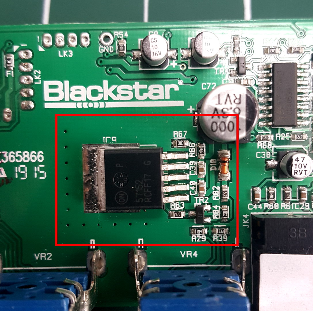
Here's some photos of the Blackstar official mains power brick, the amp rear power inlet and Rear Board, and the Main Board components involved in regulating power to the Fly's various amp stages. I've also re-included a shot of the Rear Board since you'll remember this is where power actually gets into the amp (from either batteries of external PSU).
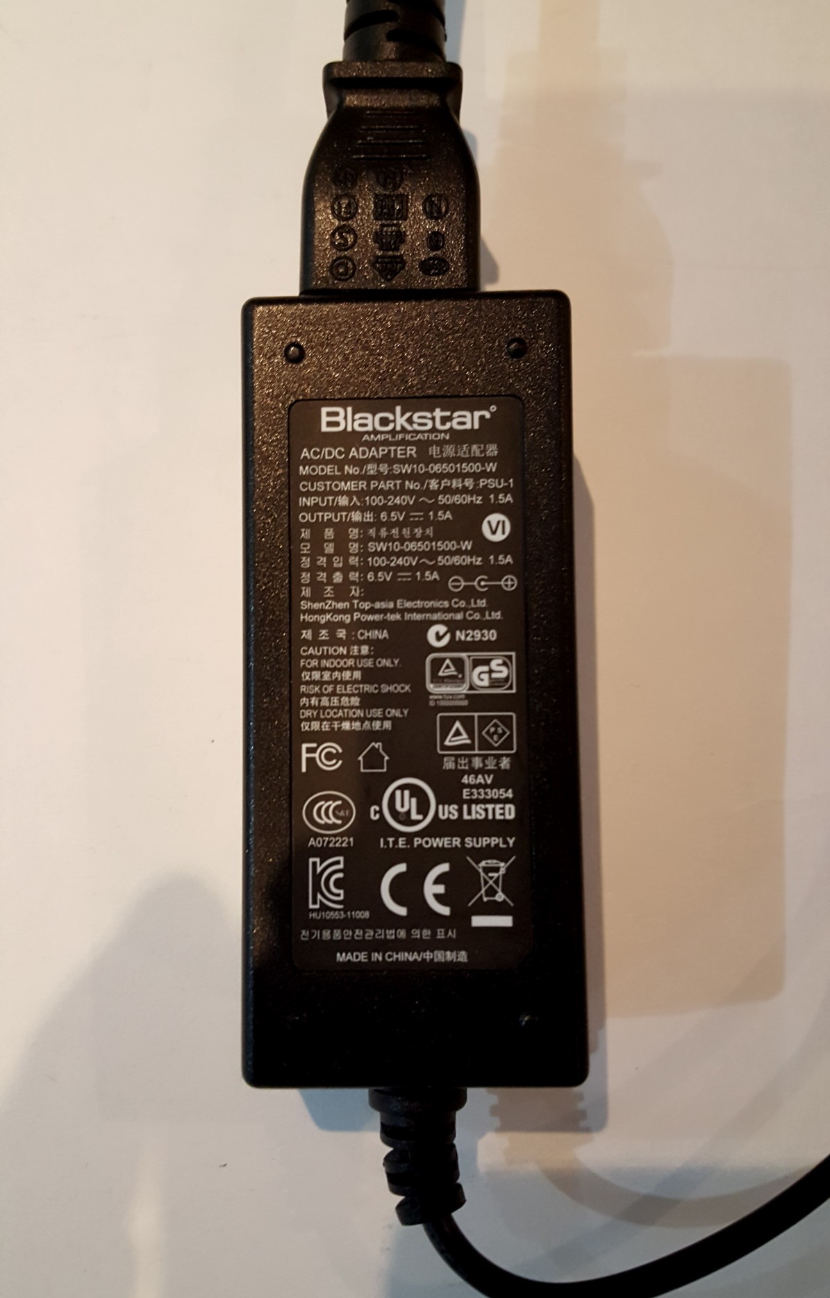
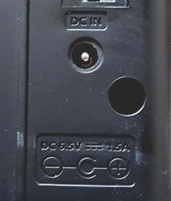
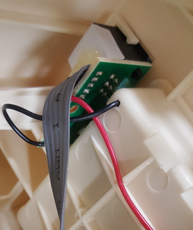
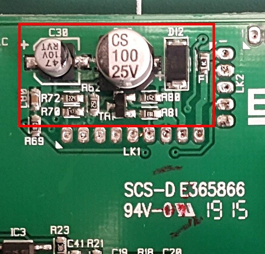
Power arrives at the back of the Fly from an external PSU via a 2.1mm male jack with inner *positive* (yes watch out for that one folks). I'll say more on the external PSU spec later. When this is plugged in it disables the 6x cell battery compartment. The Rear Board deals with all that switching and provides +V and 0V (i.e. battery negative) via two cores of the ribbon to the main board (see discussion and Rear Board schematic way back here).
Looking at the datasheets for the Fly's integrated circuits, for example the PAM8304 Power Amp (Speaker Board IC1), the TPA6110A2 Headphone Amp (Main Board IC6), and the PT2399 Delay (Main Board IC8, shows that they don't take too kindly to supply voltages much above 6v. This partly explains the presence of the 57152 voltage regulator chip (Main Board IC9). The designers needed to be sure the voltage from either batteries or external could never go above 6v so the whole thing didn't fry (creating that lovely foul smelling smoke you get when an IC incinerates). The voltage regulator is also there to help iron out wobbles in the supply voltages (that's why its called a regulator - clever eh!).
You'll see the datasheet calls IC9 a "VLDO". That means Very Low Drop Out, which refers to how close the input and output voltages can get to each other before the IC stops regulating. Regulators need a bit more voltage on their inputs to be able to go a bit up and down to keep the output voltage stable. I measured the voltage coming out of IC9 and it was about 5.2v telling me what this voltage regulator is set to. I say "set to" because the datasheet for this IC says it can provide a voltage between 1.24v and 13v, determined by the feedback to the ADJ pin. The Blackstar uses the circuit in Fig 22 of the 57152 datahseet where the ADJ pin gets a proportion of the VOUT set by 2 resistors (in the Fly R66 and R67).
Schematic and circuit analysis for the internal power supply
I traced out the circuit for the power supply as best I could, although there are a couple of components I'm not sure about as I'll explain later. Here is the schematic I got, including some stuff already shown on other schematics.
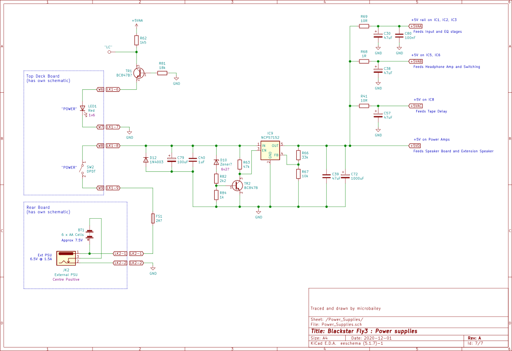
Main Board power supply and distribution
The power supply is a mostly conventional design with the power coming through FS1, a board mounted protection fuse (sorry don't know what rating it is, and I don't want to blow it to find out :) ), a "Power" switch (mounted on the Upper Deck Board), and into IC9 after a couple of filtering caps C79 and C40. Caps are used like this all the time in electronics, across power rails. They're called 'decaps' (decoupling capacitors). Smaller caps are there to deal with higher frequency supply currents, and large caps are there to act as a resovoir when there are large current spikes, which evens out bumps in the voltage.
IC9 is set to a voltage using the circuit from the datahseet shown here, and the values of R66 and R67 give:
VOUT = 1.24 x (1 +33k/10k) + (ignore this bit since R67 is less than 15k) = 5.33v
Finally C39 is across the IC9 VOUT and GND to keep the regulator stable under all conditions. If only it was so easy for the rest of us to keep stable under all circumstances.
IC9 has a max rated current output of 1.5A which might seem unexpectedly high for a tiny portable 3W amp like this, until you realise that the Class-D power amp (Speaker Board) can demand some hefty current for very short periods, when it pulses the speaker current on and off. I'm sure this is the main reason for a 1.5A regulator. The opamps and other ICs will take next to no current, but the Speaker Board will have shark peaks of current demand. And let's not forget there is potentially another Speaker Board in the Extension Cab (for stereo) .
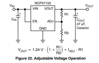
57152 datahseet extract : Adjustable Voltage Regulator
IC9 has an enable pin EN which shuts the regulator down (and VOUT) when it is taken to near 0v. This pin is held up to VIN voltage by R63 and can only go to 0v if TR2 turns on. D10 in this circuit is one of the components I'm not sure about. To me this circuit only makes sense if D10 is a type of diode called a Zener so I've drawn it like that in the schematic (short tail on the cathode bar indicates it's a Zener). Zener diodes behave like a normal one-way diode when voltage on the Anode is more + than voltage on the Cathode (end with the band). However, when the voltage is reversed, a Zener diode blocks current UNTIL a magic voltage is reached where lots of current starts to flow. You could think of it as an asymmetric diode, turning on at 0.7v one way, and at a much higher "zener voltage" the other way. If D10 is a zener then I don't know what its magic voltage is.
But I could take a guess.
To turn on TR2 we need at least 0.7v across its emitter (e pin) and base (b pin). R82 snd R84 divide down the voltage at the anode of D10 by around 3 (for a formula to work that out see this web page). That would happen if the voltage at D10 anode is 2.1v or above (3 x 0.7). In turn that would happen if D10 allows current to flow through it, which means it reaches its zener voltage. That must be at least the VIN - 2.1v so let's say about 6Volts?? (6.2v is a standard Zener value). TR2 turning on pulls the EN pin on IC9 towards 0v, so turning off the regulator. So I guess this circuit is there to shut down IC9 when too much voltage comes in, for example if someone plugs in the wrong voltage external PSU. I could de-solder D10 and measure to see if its a zener but don't have time right now (means I couldn't be bothered).
On the subject of plugging in the wrong external PSU, D12 is there to offer some protection if a plug with a negative centre is plugged in. It will bypass IC9 and blow FS1, but at least the Main Board won't fry (if you're lucky).
Before leaving the VLDO, IC9, I should mention that there is a limit to how much voltage should be given to its input. The limit is lower than you'll read in its datahseet.
You see,
Power (i.e. Watts) = Current x Voltage x Voltage (yes, that isn't a typo its voltage times voltage, or voltage squared as the maths guys say)
The reason power matters is it turns into heat and so IC9 gets hot. You might have noticed there is a big metal tab on IC9 which is soldered firmly a big chunk of copper on the Main Board top-side, to try to get rid of all that heat. With bigger currents (due to the power amp) the voltage VIN - VOUT easily affects the heat generated. It's why Blackstar have specified a 6.5v power brick, it limits that voltage drop across IC9 to around 1.5v, and so controls the heat.
I haven't talked about the circuit around TR1 which drives the "POWER" LED on the Upper Deck board . This circuit is obviously there to provide current into the LED and light it up (and a LED is just a type of diode which glows with a colour when it conducts). TR1 is the other component I'm not sure about. I can't see how this circuit can work if TR1 is an NPN transistor (for the curious, NPN vs PNP are explained well here: https://www.electronics-tutorials.ws/transistor/tran_3.html) however, on the board it measures as an NPN. In any case TR1 must turn on when the +5V rail is up (I mean switched on) and provide a steady current to light the red LED . Blackstar have added a testpoint on the board here, labelled "LC" on the PCB legend. I'm not really sure what it's for since the LED doesn't need any special manufacturing test - it will be on when the power is applied. It either works or doesn't.
Update on the LED circuit: The consensus on freestompboxes by The G and Manfred is that TR1 must be a PNP and that this is a circuit to provide a constant current to the LED. When I put my amp back together so it works (hopefully), I'll probe some voltages to see if this is the case.
Power supply filtering
Looking beyond IC9 VOUT I traced a set of RC (resistor-capacitor) low pass supply filters which generate various versions of the +5V rail for parts of the Blackstar's circuit. Specifically these are
- R69+C30 (supplies IC1,2, and 3)
- R68+C38 (supplies IC5 and IC6)
- R41+C57 (supplies IC8).
You might think a low pass filter is just for audio but in fact they're used all over the place in electronics, and in this case on power supply rails. These filters have a cutoff frequency (see the calculator link I put earlier) of 33Hz or 334Hz depending which RC pair you look at. Why filter a DC voltage you wonder? It's because the DC wil also have some AC signal (called ripple when its a supply) on it from the audio. These filters allow the 5V DC to pass, but block the AC ripple at audio frequencies.
Of course like everything in life there is a trade-off. Adding a resistor in series with the supply causes a DC voltage drop (Herr Ohm tells us voltage = current x resistance).
So the bigger the R the more the V. That's why you'll notice the resistor values are really low (1 to 10 ohms) and the cap values are really big. When it comes to the supply for the Power Amp (which needs a lot of current as we said earlier) there is no resistor just a big cap. Of course there is a resistor really - its the resistance of the copper PCB trace, So this supply has an RC filter too.
This way of filtering supplies for different stages of an amp is very common in electronics and is a cheap method of providing some isolation of each supply so the noise from one circuit doesn't couple into another. An example would be if the clock of the delay circuit coupled, via the supply, back into the input stages and caused an annoying noise in the speaker. These RC filters help to stop that happening.
Let's talk about Grounds. Not Anfield or Old Trafford. Not Camp Nou. No this is about electrcial grounds, "Gnd" for short or just plain old 0v.
Something Blackstar designers have definitely taken some care about is how Ground has been routed and connected on the board. As usual for PCBs, ground on the Main Board is mostly copper fill in between all the other traces - what's known as a Ground Plane.
Two (main) reasons for doing this:
- It helps to avoid big areas with no copper in the PCB manufacture process (big areas of no copper is a bad thing)
- Large wide areas of copper have very low resistance (Ohms) to electric current (this is a good thing)
Why is No.2 important for Ground? Well the higher the resistance of a wire the more voltage you get from one end to the other as a current flows through it (that's Ohm's Law again). Having a super-low resistance means 0v is about 0v everywhere on the PCB, not just where the power supply connects to it.
Blackstar also took care of where they connected the circuit parts with high current to the Ground plane.
Look at the schematic fragments here, where the Main Board and the Speaker Board grounds and signals connect via the ribbon:
Interlude: Ground routing
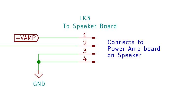
Fly Main Board connection to Speaker Board
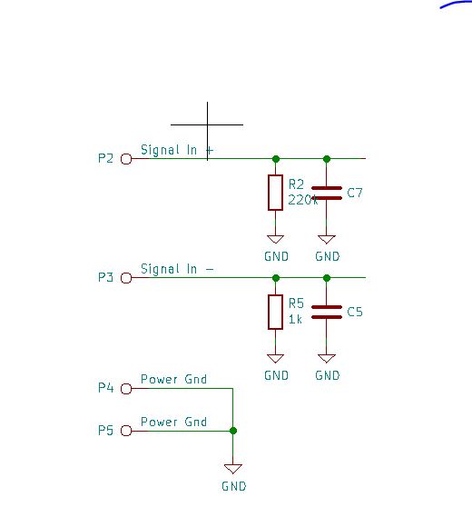
Fly Speaker Board connection from Main Board
Remember the Speaker Board has a Class-D power amp IC and this will take a lot of current in extremely fast spikes as it switches current to the speaker (See What is a Class-D amplifier?). This can create a lot of noise. Noise here meaning electrical noise - voltage, like the supply ripple mentioned earlier.
Current goes round in circles. A bit like "what comes up must come down". If a current flows into something, it must come out again somewhere (yep there's a name for that law too - Google "Kirchoffs First Law"). In this case it comes out of the power amp Ground connection on the Speaker Board and back to IC9 and beyond.
We don't want these return current spikes to create voltage spikes on the audio signal going to the power amp. To avoid this Blackstar have used a technique called "star connected ground" where the supply ground only connects to the IC9 ground very close to the same point the signal -ve to the Speaker Board (Power Amp IC) connects.
To illsutrate. Look at how Blackstar didn't wire up to the Speaker Board ground (on the left) and how they did wire it (on the right)
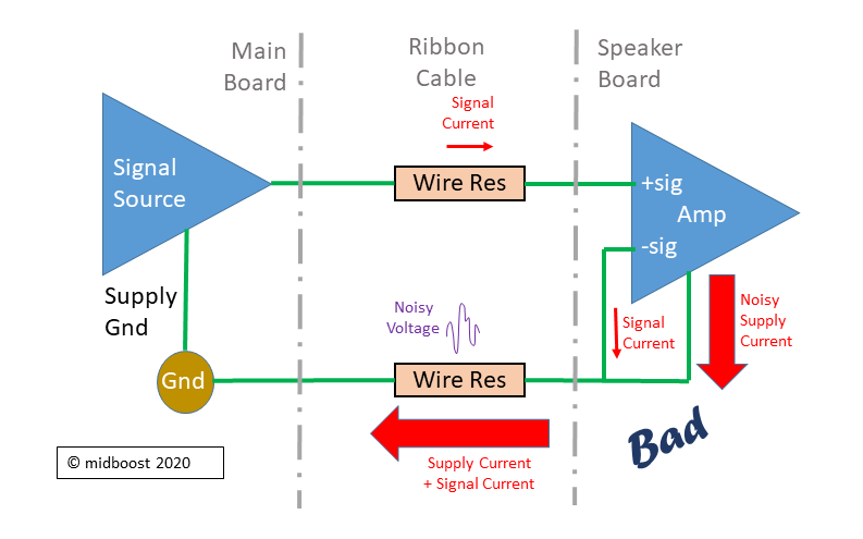
The way the Main Board and Speaker Board grounds are NOT connected
Imagine Blackstar had made the preamp to amp Ground connections as shown in the Bad diagram. Here all the spiky current from the Amp flows through the Ground Wire Resistance and makes spiky voltages. These get seen at the Amp input -sig and so get amplified (the Amp amplifies the difference between -sig and +sig). This adds noise to the signal.
By contrast, in the Good Diagram, the Amp supply current still makes spiky voltages across the Ground Wire Resistance, but none of this noise voltage is seen at the Amp -sig input. Now we get signal without noise.
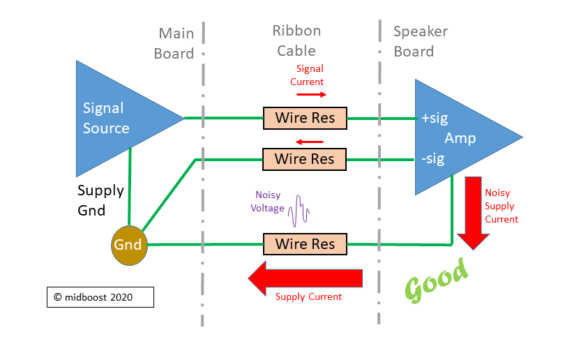
The way the Main Board and Speaker Board grounds ARE connected
Hopefully those diagrams help explain why Blackstar (and in fact all decent amplifier designers) take care about where they connect their Grounds as it makes a difference to what you hear in the speaker. Everything is relative. Ground is not always 0v, it can move around (as we can see in those diagrams). That is a whole other topic but a real big problem in audio. Anyone who has had a ground loop with their pedals or their mixing desk knows what I'm talking about.
Blackstar Fly3 Power supply FAQs
While writing this blog, I've been emailed a few questions about the Blackstar Fly3 power supply so I'll try to answer them again here:
FAQ1: Can I use a regular pedal 9v wall wart, or a pedal board 9v PSU, to power the Blackstar Fly3?
Answer: No.
As we saw the heat in IC9 gets too high if the input voltage goes up too much. We also saw there is (probably) protection against higher input voltages, but I wouldn't count on it. Anything more than the batteries provide (around 6 x 1.2v when loaded with the circuit) might trip this protection in the Fly, or even worst do some component damage.
Another thing to remember is we need a 1.5A supply. That is far from your standard stompbox wall wart. So unless you have something which matches the Blackstar 6.5V 1.5A supply don't try plugging it in.
And don't forget the DC plug polarity which is the opposite way around from stompbox PSUs.
FAQ2: I've plugged my guitar/pedals into both the Blackstar Fly3 and into another guitar amp, and I get hum. Is my amp broken?
Answer: Not necessarily. You possibly have a ground loop. Wow. This is a huge subject - I'll give a brief answer!
If you are using the Blackstar Fly3 offical power supply the -ve of the supply jack (which on the Fly is the outer ring) is connected to earth (the electric company's Ground) on the mains cable which plugs into the PSU brick. This earth connection is pretty usual, for safety (shock protection) reasons.
Now this matters because it connects your Gnd in the Fly, which in turn is the shield on your guitar cable, to earth. That's great for safety (your guitar can't accidentaly get 100s of volts AC connected to its strings - hardly possible with modern amps but a real danger in the 1960s/70s). It's not so good for the Grounds though.
Imagine you now have another piece of gear (amp, mixer, pedalboard etc) which also has its Ground (0v) connected to earth through its mains power supply. And you have a standard guitar cable connecting the Fly to this other piece of gear.
- Now the Ground in the Fly has become connected to
- Ground in the other gear (via the guitar cable) which in turn is connected to
- Earth via its power supply cord, which is connected back to
- Ground in the Fly via the earth wire in its power supply cord, which is conencted to
- Ground in the other gear (via the guitar cable) which in turn is connected to
- ... I think you start to get the idea ...
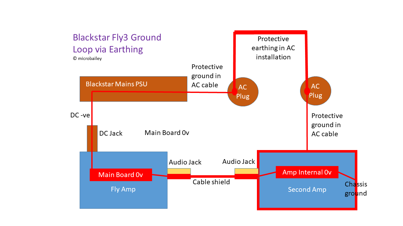
Example of guitar amp ground loop through earthing
You got yourself a ground loop - as illustrated in this picture.
There is a huge circuit made from a conductor (all the parts of the cables) going in a complete loop.
Big loops of wire are fantastic for picking up radio signals, mains hum, fluorescent lighting, anything which creates a magnetic field really. You might have come across loops installed for deaf aids which work the other way round, they transmit so anyone with a deaf aid can pick up the signal.
This Ground loop will pick up all manner of crap and feed it straight into your audio chain. Its even worse because the earth wires run alongside the mains AC voltage in the same cable sheaths.
The answer to this is to break the loop somewhere (but hey, remember, you must never break the chain).
(non-life threatening) ways to break the loop are:
- Use magnetic isolation on one of the power supplies - either
- on the mains side (so the earth no longer connects and the mains AC voltage "floats", or
- on the 6.5v DC to the Fly. Btw - I'm not aware of any piece of kit which can isolate 6.5v at 1.5A
- Isolate the audio cable between the gear using an audio isolation transformer - now the Ground is now longer connected. This can colour your sound though.
- Isolate the audio cable between the gear by disconnecting (aka "lifting") the Ground on the end where the signal goes into something
On solution No3, its often the simplest, but it does mean you need to have a modified cable or a ground-lift switch in your gear. The audio shield is maintained because it is still connected to Ground at the source end (where the signal comes from).
As a side note, the wall warts used for pedals almost never connect Earth to supply -ve. In fact some just have a plastic pin or tab for earth so there is no earth connection at all.
Upper Deck printed circuit board
Before delving into the speaker stuff, I thought it was worth adding a circuit schematic for the Upper Deck board. It's been mentioned a lot, and you've already seen bits of it in the Main Board schematics where the components are part of those circuits.
It holds the pots and switches which are to the back of the Blackstar Fly3 control panel (looking from the front if that makes sense ??). That means:
- Overdrive latching push switch
- Delay Time pot
- Power on/off latching push switch
- Power on LED
The board is supported off the Main Board with an L-shaped aluminium bracket which fits over the pots on the Main Board. The Upper Deck Board connectes to the Main Board LK1 via a 9-way flat ribbon.
I would say there's scope to add something like a switch to this simple board since there's lots of empty real-estate. Main problem is connecting a switch back to the Main Board which would need a second cable or wires.An extra switch could enable some DIY feature like changing a resistor value in the preamp for EQ change or extra boost.
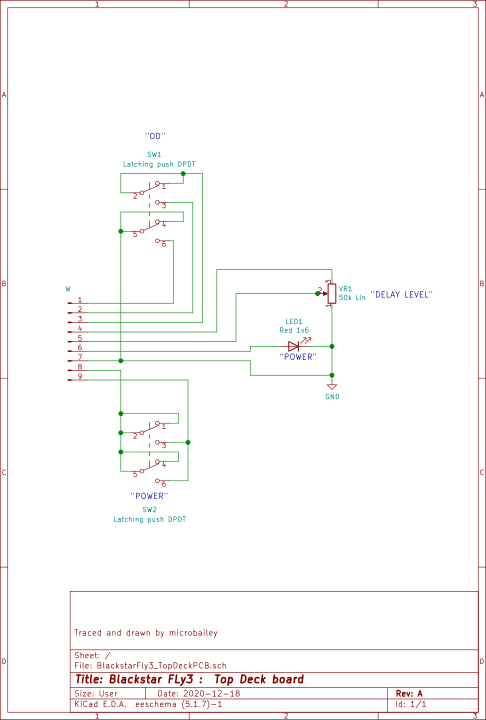
Upper Deck board
The Speaker and the Amplifier Case
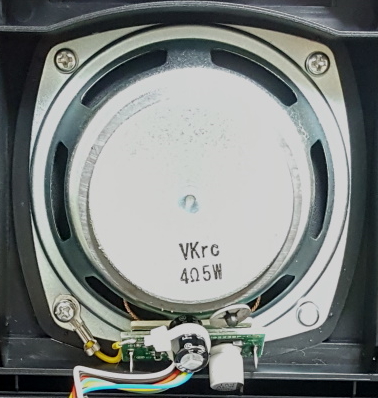
Speaker driver unit in Blackstar Fly3 guitar amplifier
The speaker in this amp is a bit like the PSU. On the surface, not much to say - its a 3" (75mm) driver with a visible ceramic magnet, of the type you might see in a small radio, a Bluetooth speaker, or fitted in a car door.
The markings say "VKrc 4ohm 5W" so it's a 4 ohm 5W speaker. By the way, the 4 ohms means 4 ohms DC (direct current) resistance. At audio frequencies the resistance will be much higher than this.
Of course as every good guitarist knows, the speaker is a major part of any combo amp's character. This is because speakers are inherently non-linear devices. That's a fancy way of saying they don't behave the same for all input signals. In fact speakers tend to do whatever they want. Most of us know that our guitar amp will sound very different with a Celestion Greenback or a Jenson or a Patrior Texas Heat in it (just to ention a few). These speakers have different sounds for all sorts of reasons, but one of the main ones is that the construction and electrical characteristics mean certain frequencies peak or dip.
So the speaker is a sort of hard-wired EQ in itself, and its the reason a guitar plugged straight into a desk or PC and recorded direct sounds nothing like a mic'd up speaker cab.
To me the Blackstar speaker looks quite similar to this 2.5 inch model https://www.visaton.de/en/products/fullrange-systems/fr-7-4-ohmI would have thought Blackstar had the Fly3 speaker designed to their own spec, which means it's frequency response will be shaped to what they specified.
Anyway to give an idea, here is the spec for that Visaton off-the-shelf speaker:
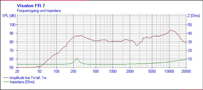
Visaton FR7 speaker frequency response (a speaker similar to the one used on Blackstar Fly3)
For those of us who don't speak fluent German (I did it at school but can only remember some pretty useless words like "Wohnzimmer" now) I think we can guess that "Impedanz" means Impedance, and "Amplitude" - well I'll let you work that one out. Going up the chart is SPL which stands for Sound Pressure Level i.e. how loud the thing is. Along the bottom from left to right is the frequency in Hertz (a German scientist's name - which fits well with a German made loudspeaker).
You can see its fairly flat apart from a peak around 250Hz and another around 10kHz. The response rolls off quite sharply below 200Hz. In the Blackstar case, as the speaker is a half-inch bigger (and size matters) I'd expect that roll off to start a little lower down. As we'll see that lack of bass is key to decisions Blackstar took with the speaker and the case.
The speaker size was probably determined by the maximum size they wanted the whole amp to be. A 4" or 5" cone would have been nice, but wouldn't have fitted into a bookshelf sized amp box.You might have heard of "Hofmann's Iron Law" (of German descent perhaps?) which crudely put says if you have a small speaker cab, and you want good bass, you need a powerful amp. Well we've got a Class-D power amp with good electrical power, so that's a start.
There is however another industry trick Blackstar have pulled to improve that poor bottom end.
Amplifier plastic case / speaker enclosure
The Blackstar Fly3 has good cleans even at some volume. But to get good clean guitar audio we need bass otherwise we just get 'honk, honk'.
That's where the funny plastic tube shown with the big red arrow in the next picture comes into play.
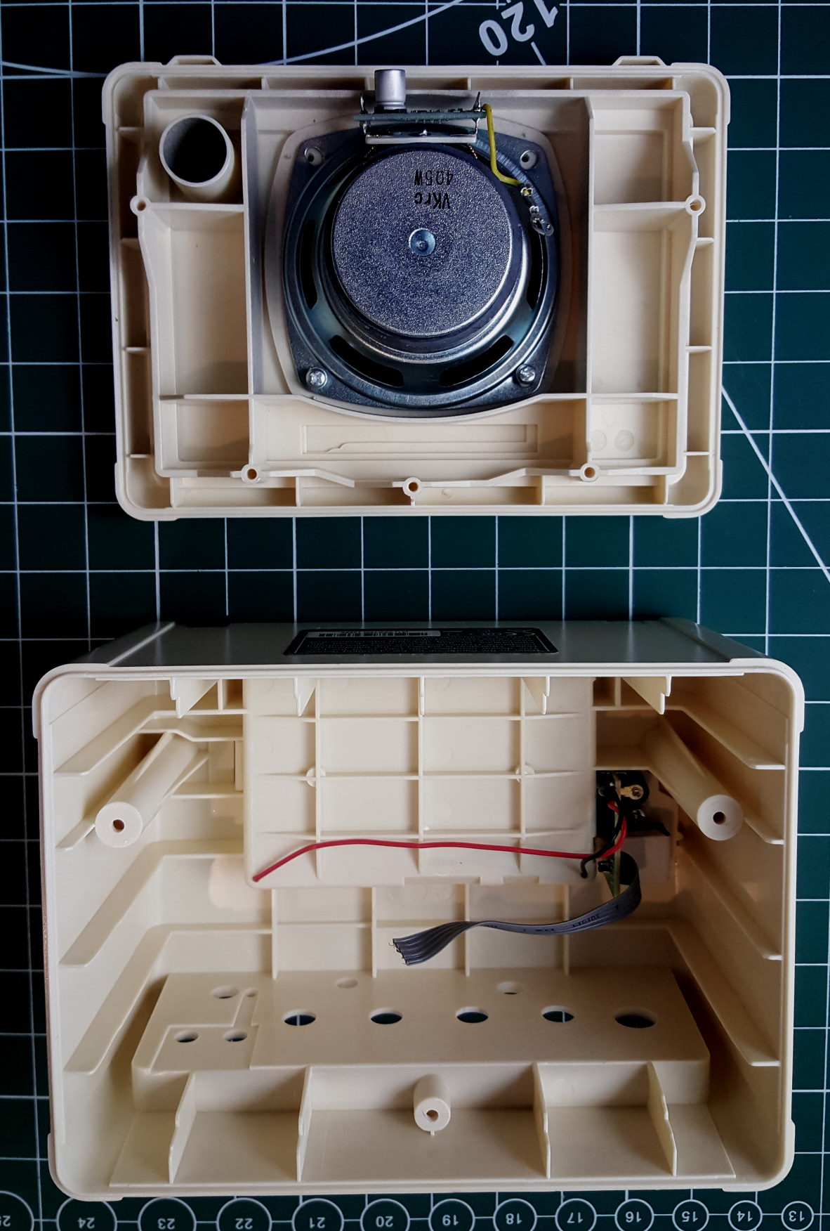
Blackstar Fly3 empty speaker enclosure
What's that?? Did they forget to cut off a piece of the plastic moulding?
It's called a "Port". Does it take us to another dimension? Sadly no. But it does add bass.
Here's a picture I borrowed from Wikipedia, showing a ported speaker cabinet.
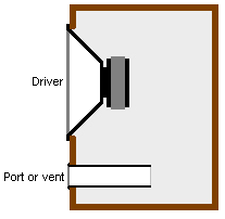
Ported speaker (borrowed from Wikipedia)
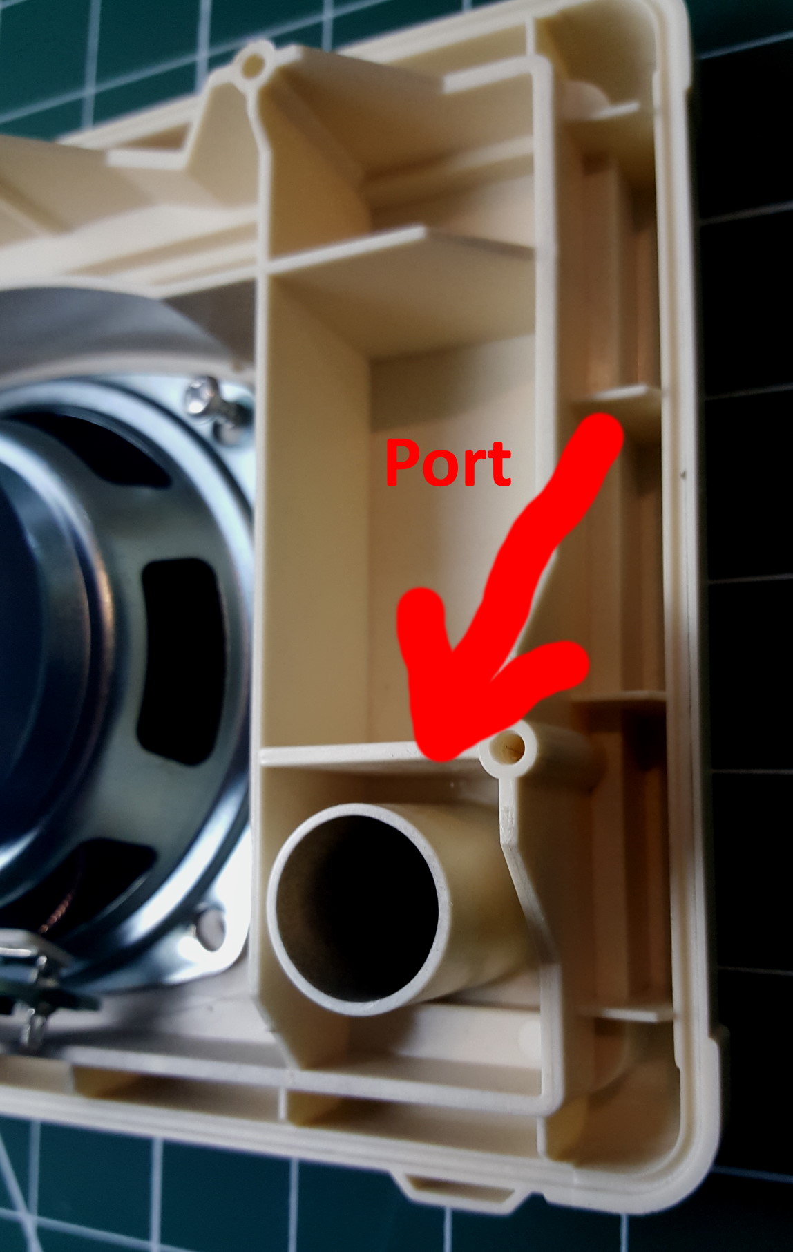
Bass reflex tube in Blackstar Fly3
The idea is you seal the speaker cabinet except for a tube with a specifc cross-section and length. You can imagine that when the speaker vibrates with sound waves, all the air inside the cabinet (in this case the box the Fly is in) vibrates too.
Now what happens when you blow over the end of a pipe or a bottle (go on try it!!) - yes you get a note, and importantly it can be quite a loud note. That's how pan pipes work, I used to have some somewhere but they're long lost now. This effect is called Helmholtz Resonance (keeping the German theme going) - the column of air in the pipe starts vibrating at a particular resonant frequency which depends on the dimensions of the pipe.The sound hole in an acoustic guitar, or a drum shell uses the same principle.
There's a bunch of maths (sorry math if you are in the USA) which speaker designers use to make ports in their cabinets resonate at the frequency they want.
Here's some online calculators to play with: http://www.mh-audio.nl/Calculators/WVC.html
The port tube in the Blackstar Fly3 measures 16mm dia x 25mm long. The whole amp case interior measures 160mm x 115mm x 80mm minus the space the battery compartment takes (100mm x 65mm x 20mm) gives an air volume of 0.001342 cubic meters = 1.342 Litres (sorry again if you are in the USA!).
If I plug those numbers into that "Calculate Tuning Frequency" calculator, together with some assumptions about the air at the ends of the port, the typical speed of sound, my shoe size etc., I get a resonance frequency of 114Hz. Handy number huh? It means we get a new SPL peak at around 110Hz, just where this small speaker can't shift much air. In short it makes the speaker and cab sound much bigger than they actually are and gives us deeper bass.
Try blocking that hole up and see what it sounds like then. The exact same trick is used in Hi-Fi speakers and car woofers to get massive bass.I expect Blackstar engineers used some CAD software to design the Fly3 amp case so the speaker sounds its absolute best in it.
Well you never thought there could be so much science in a lunch box with a hole in it did you?
Wrapping it all up (and putting it back together again)
Well when I opened up this tiny practice amp I didn't really expect to find a whole lot inside. I thought I'd see a cheap linear power amp chip, a couple of op-amps at most, maybe some clipping diodes, and that's about it. Or even less interesting I thought I might find a custom chip with a big Blackstar logo on it.Instead, I've found a consumer type Class-D power amplifier chip, a sophisticated clipping circuit which is love-child of a Tube Screamer and a DS-1, a separate headphone amp IC, and a whole bunch of carefully designed op-amp based EQ filters.You get a lot of circuit for your money in a Blackstar Fly3, and its obvious the engineers went to some trouble to optimise the sound from that tiny 3 inch speaker.
Another thing I discovered is the possibility of mods.
- The Main Board in the Fly3 has plenty opportunities for tweaking component values in all those filters to get more bass, more mids, more anything.
- There's scope for trying different clipping diodes to see how they affect the overdrive sound.
- The Upper Deck board has vacant space for an extra switch or socket to add some cool custom feature (hmmm I'm thinking about that ...)
- The optional Extension Speaker cab is a 6 volt powered speaker full of space waiting to be turned into something other than a Blackstar Fly3.
To finish, here is a block diagram of the Blackstar Fly3, to show how all the circuit parts fit together. This might be useful especially as I wrote this all backwards, starting from the speaker and working towards the guitar input.
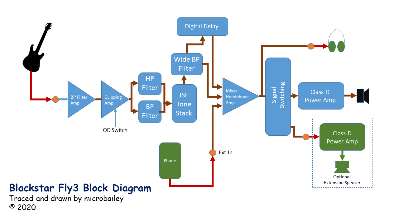
Blackstar Fly 3 block schematic diagram
If you have been reading all this from the start - go collect a beer or two - You deserve it!!
All that remains for me now is to take my Blackstar Fly3 amp, in its many bits, and solder it all back together to make some lovely sounds again.
That's All Folks!! (for now)